
15.02.2018
Constructing the crewed Orion – EM-2 spacecraft deep into welding operations
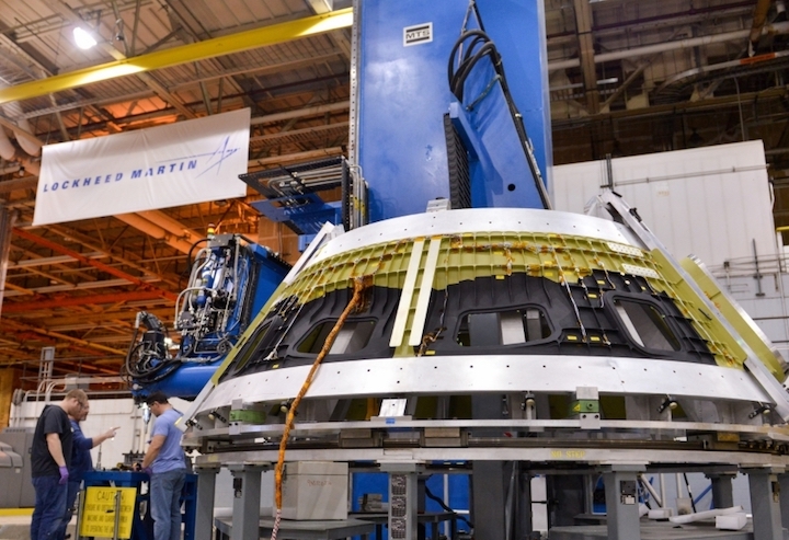
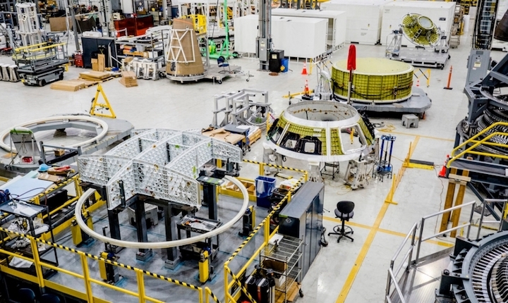
Construction of the living and working area for the first crewed Orion spacecraft is well underway at the Michoud Assembly Facility (MAF) in New Orleans. Building on lessons learned from previous construction, Orion prime contractor Lockheed Martin has already completed four of the seven welds necessary to assemble the crew module pressure vessel.
Current schedules call for the completed pressure vessel to be shipped in September to the Kennedy Space Center (KSC) in Florida, where it will be outfitted to fly on Exploration Mission-2 (EM-2).
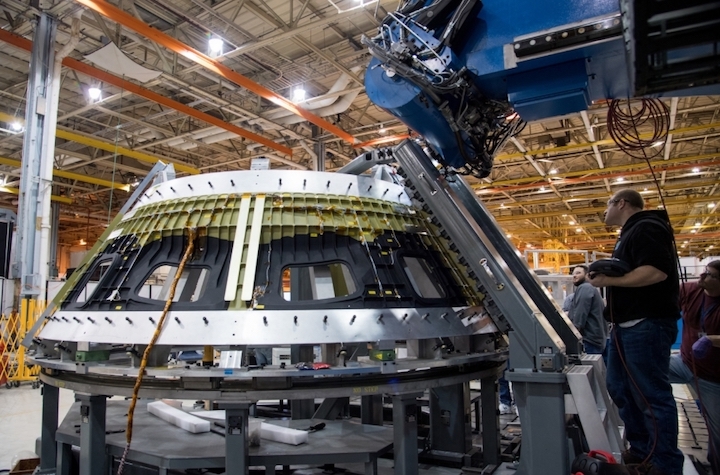
“We’ve done the PV1 weld — that’s the tunnel to the forward bulkhead — [and] we just completed the three cone welds,” Blaine Brown, Orion Crew Module Engineering Manager for Lockheed Martin, said in an interview with NASASpaceflight.com. “[The] next one that we’ll do is the aft bulkhead to the barrel.”
At the time of the interview on February 7, Brown also noted that the aft bulkhead was the last piece to arrive at MAF: “The bulkhead is in the process of being transported to Michoud today, actually, and the barrel is already at Michoud.”
The crew module pressure vessel consists of seven major welded components: a tunnel, three cone panels, a barrel, and two bulkheads. AMRO Fabricating Corporation in South El Monte, California, manufactures the three cone panels and Ingersoll Machine Tools in Rockford, Illinois, manufactures the other four components.
EM-2 will be the first Orion mission to fly with crew, with its mission currently scheduled for no earlier than 2023.
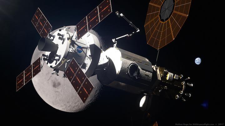
“It’s really historical, not just from a technology standpoint,” Paul Anderson, director of Orion EM-2 production at Lockheed Martin said. “It is the future vehicle of NASA to do space exploration, but this specific EM-2 mission will take humans further than any time in history.” The EM-2 mission is currently planned to be a circumlunar flight.
The pressure vessel is the structural core of the crew module. Other elements such as systems for thermal protection (the heatshield), propulsion (attitude control), and landing and recovery (parachutes and flotation) attach to the outside of the pressure vessel, in addition to other primary and secondary structures.
It is also the crew cabin — the living and working area for the astronauts on the mission. Most of the time, a sea-level atmosphere in the pressure vessel will be maintained for the crew. Inside the pressure vessel are areas for crew systems such as flight controls, communication and information systems, seating, storage for food, clothes, and equipment, a galley, and a toilet.
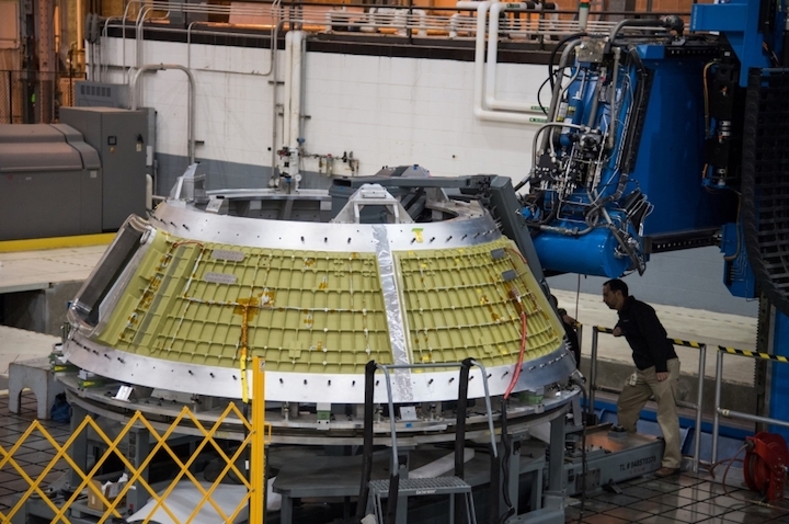
The pressure vessel is welded together in a sequence of welds. With the tunnel joined to the inside of the forward bulkhead and the cone formed by those three panels, those two sub-assemblies will be welded by joining the outside of the forward bulkhead to the top of the cone. Separately, the bottom of the barrel will also be welded to the aft bulkhead.
Once those welds are complete, the pieces will almost be ready for the final weld. “The final weld is the closeout weld, where we weld the cone to the barrel,” Brown said.
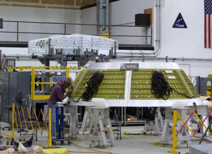
Before that final weld, the other major structural component has to be added to the aft bulkhead, called the backbone assembly. “It’s a structural reinforcement, as well as providing basically areas where we can then put the crew equipment, stowage, all that kind of stuff,” he explained.
“We’ve got running crossbeams through there, and it also serves as a partition. That’s where our lockers go and it’s also where you’ve got the area where the toilet is and also the galley for the crew.”
The backbone assembly is a bolted structure consisting of nine pieces that are assembled prior to being installed inside the pressure vessel. “We actually have a very nice tool that we can build that whole backbone up, separately, get it all in alignment, get it all precise, and then it fits right into the barrel/aft bulkhead area,” Brown noted.
The backbone is also bolted into the welded aft bulkhead/barrel assembly.
The EM-2 pressure vessel is the fifth structure to be constructed at MAF. The first two Ground Test Article (GTA) and Exploration Flight Test-1 (EFT-1) structures were pathfinders for the program in terms of production, processing and handling, and flight.
Taking the lessons learned from the GTA structure and EFT-1 vehicle, the pressure vessel was improved to reduce the number of parts and overall weight while maintaining its required strength. From the GTA pressure vessel (the first) to the EM-1 pressure vessel (the third), the design reduced the number of components from thirty-one pieces to seven and reduced the overall weight from 3900 pounds to 2700.
The lessons learned have also led to improvements being fed back into manufacturing, assembly, and production.
“We’ve really been through this multiple times already,” Brown noted. “The EM-1 and structural test article (STA) [pressure vessels] have been basically following the same process, so we’ve really wrung this [process] out and applied lessons learned in doing this.”
“It had taken three weeks to a month to get through these welds like on the cone [panels],” he explained. “Originally even longer, because we were [new to] getting the alignments [correct] and here it was like a week and a half to get through the three of them. As you would expect, you learn on each of the builds and we’ve done it many times now.”
“The entire MAF operation [has] gone extraordinarily well,” Anderson added. “Whether it was on the STA, EFT-1, [or] EM-1, every time we do this we apply whatever lessons learned to tooling, whether it’s tolerances to manufacturing. All of this we have started to see pay dividends.”
“We have really seen improvements [in] how well these things have gone together,” Anderson continued. “The supplier performance of the seven major elements, whether it was Ingersoll or AMRO, has been I would say significantly better. Just because they’ve learned as well, there are all these similar operations within their factories.”
“And we’re really excited about that as we head into the production phase of this contract that will hopefully be started later this year. So we’re really starting to see efficiencies, time reductions, and cost reductions, and it’s really exciting to see.”
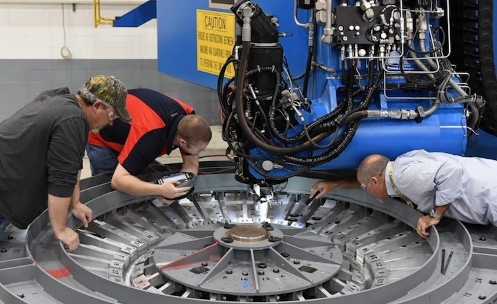
Each of the pressure vessel welds has its own tool where the parts are welded. “There is specialized tooling for each one of these [welds] that we custom fabricate,” Brown explained.
“The actual weld head itself [is] basically the same, but we have different tooling to basically line up each of the different parts to get the weld interfaces in exactly the right alignment and hold them into place while we go do the weld sequence.” Self-reacting friction stir welding is used for each of the welds.
After welding, non-destructive evaluation (NDE) is used to inspect them. “[We use] ultrasonic inspections there to basically look for any kind of defects or flaws that are in those,” he said.
Brown also explained another work item for some of the welds: “We do what we call ‘planishing.’ [That] is where you literally pound it with a hammer,” he explained.
“That’s basically stress relief on those particular welds. We’ve worked with that quite a bit in the past to identify which are the critical welds that we need to [remove] any kind of residual stresses that come from the weld process and the fit-up process itself.”
Once the pressure vessel is fully welded, bolted, and inspected, it will be cleaned and prepared to ship from MAF to KSC. “There’s a shipping tool that we have, a fixture,” Brown said. “You basically wrap it all up good and tight inside, and then you put it in this shipping crate.”
The pressure vessel can be shipped to KSC either by ground on a truck or by air using NASA’s Super Guppy aircraft. “We’ve done both ways, truck and Guppy,” Brown added.
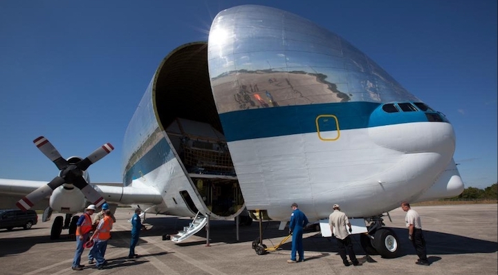
“[If] it goes on the truck, it’s then a wide load and we have a certain route, we do permits and all that kind of stuff to get it from Michoud over to KSC. Certainly, the Guppy is the quickest [but] it depends on urgency and availability of the Guppy. The Guppy is the easiest one, but sometimes it’s not necessarily available when we need it.”
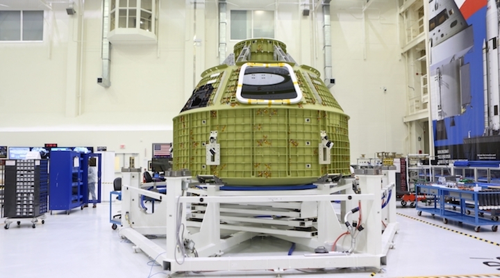
Anderson said the pressure vessel is currently scheduled to arrive in Florida in September. Once it arrives there and is transported to the Orion spacecraft processing area in the Operations and Checkout (O&C) Building at KSC, work will begin to complete the overall structure of the crew module.
“We do what we call birdcage operations,” Anderson explained. “The birdcage is literally a tool down at the O&C that houses the primary structure. It enables us to install other elements of what we’re calling the primary structure [that are] not pressure vessel related. We do secondary structure installation that’s about the first five or six months, [where] we finish out what we’re calling [the primary structure].”
One of the early processing milestones at KSC is proof pressure testing, which verifies that the pressure vessel is air-tight. The structure is sealed and pressurized above and beyond the maximum expected pressure; this verifies structural integrity and margin.
“We won’t have the final flight hatch configuration at that point, but basically we have [verified the] integrity of the pressure vessel,” Anderson added. “We’ll instrument that and so on in that proof pressure test.”
Farther into processing, the spacecraft will continue to follow in the EM-1 crew module’s footsteps.
“We’ll begin to install propulsion, we’ll begin to install harnesses, some of the ECLSS (Environmental Control and Life Support System) components, as we build up,” Anderson noted.
“We’ll do welding for propulsion and ECLSS — that’s going to be our clean room operation. Within the O&C, there’s both clean room ops and normal ops. When we do welding we have to go to the clean room.”
Quelle: NS
---
Update: 16.02.2018
.
NASA releases Request For Information for new Orion Service Module engine
NASA has released a Request For Information for a new engine the agency will use on the Orion European Service Module beginning with EM-6 (Exploration Mission 6). The Request For Information states that the engine is needed by mid-2024 in order to support the EM-6 flight of the Space Launch System, which under the currently in effect budget and operational timeline for NASA will be No Earlier Than 2027.
Orion Service Module engine RFI:
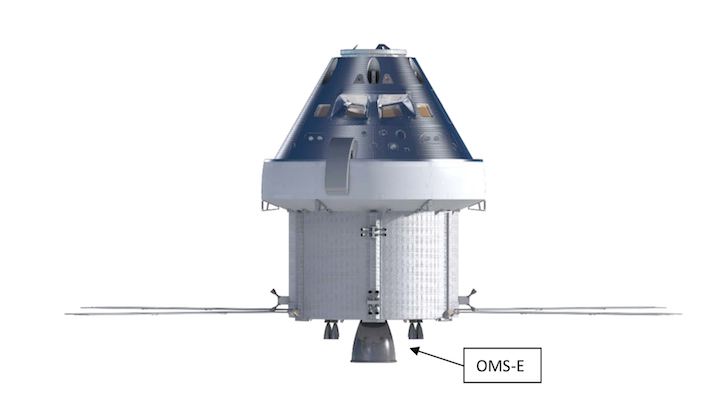
As part of NASA’s plan to utilize as much hardware that remained at the end of the Space Shuttle program as possible for the SLS (Space Launch System) rocket and Orion capsule, the agency mandated that Orion’s European Service Module (ESM) utilize the leftover Space Shuttle Orbital Maneuvering System (OMS) engines for the first five Orion/ESM flights.
The supply of available Shuttle OMS engines will run out after EM-5, currently slated for No Earlier Than 2026, as the European Service Module is expended at the end of each flight and not reused. As such, NASA requires a replacement engine beginning with EM-6, and the agency took the first step toward that replacement yesterday in releasing a Request For Information (RFI) to the aerospace industry.
“NASA invites industry to submit a response to this Request For Information to assist NASA in planning for the development of a new Service Module Main Engine for the Orion Multi-Purpose Crew Vehicle.”
All RFI responses are due by 16 March 2018 to the Johnson Space Center in Houston, Texas, and according to the RFI document, “are intended to provide input for an assessment of a new engine for the ESM with respect to the constraining performance and interface requirements.
“NASA desires a low cost replacement engine to minimize program cost and schedule impacts to the Orion vehicle. The replacement engine shall minimize development time for an engine and reduce manufacturing/production costs while still meeting NASA programmatic, technical, design, construction, and workmanship approaches and standards for human rating.”
However, because the Orion ESM has been designed to use the leftover Shuttle OMS engines, the needed replacement engine must meet strict and already determined operational constraints and a host of other already-determined requirements.
Thus, NASA’s RFI is a way to ensure the agency is following the best practices possible to keep the cost of the new engine down while still meeting all safety and timeline requirements.
Constraining parameters:
Based on the current Shuttle OMS engine parameters, NASA’s RFI for the new service module engine states that the engine must have a minimum specific impulse (ISP) of 310 seconds using already established Standard Inlet Conditions.
According to the RFI, those Standard Inlet Conditions include a fuel inlet pressure of 244 psia, an oxidizer inlet pressure of 240 psia, and a propellant temperature of 70℉.
The engine must also be able to produce roughly 6,000 lbf of steady-state thrust in a vacuum with an engine thrust roughness “less than +5% of average steady state thrust.”
Moreover, the engine must reach 90% of steady-state thrust within 0.45 seconds (+/- 0.1 seconds) of receiving the “on” command while also not exceeding a peek overthrust of 150% of the mean steady-state thrust upon engine start.
The new engine must also use an oxidizer to fuel mixture ratio of 1.65 (+/- 0.03), carry a maximum weight of “~284 lbf” and a length of roughly 79 inches (with a max “head end to gimbal” length of 23 inches).
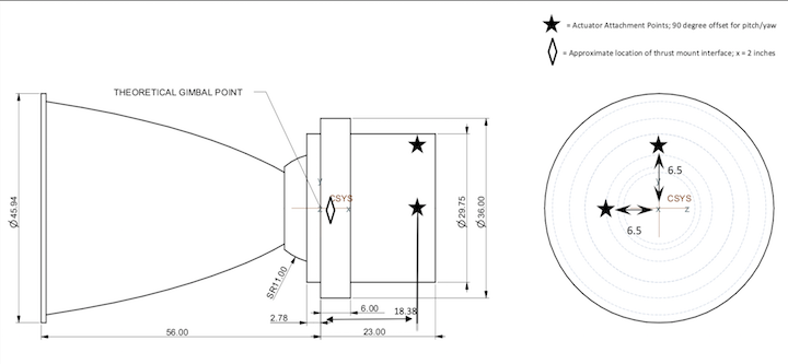
The current Shuttle OMS engine “gimbal to nozzle exit” length of 56 inches can be varied on the new engine, and the RFI specifically notes that if such a variance is suggested that the RFI answering company provide insight as to why.
Additionally, the engine must be able to gimbal greater than +/- 6 degrees in pitch and yaw during operation, must not exceed a maximum power consumption of 309 W, must be able to restart as soon as 240 seconds after its previous shutdown, and must be capable of supporting a mission duration of a minimum of 21 days for lunar missions and 210 days of “quiescent duration in cislunar or transit conditions.”
But the engine’s space-base and operational requirements aren’t the only points of information requested by NASA. The agency also released a set of requirements for the engine’s ground support, control of catastrophic hazards requirements, failure detection for crew safety requirements, independent confirmation of failure assessments, and reliability.
Specifically, NASA requested information on the ground handling elements for the engine, including installation, checkout, loading, cleaning, installation in Europe, testing in Europe and the United States, testing at various NASA centers/facilities, as well as launch preparations.
In terms of catastrophic hazards, the new ESM engine “shall provide failure tolerance to catastrophic hazards with no less than single failure tolerance except for areas approved by NASA or designed for minimum risk, zero failure tolerance, or integrated hazard controls.” Additionally, the engine must be able to detect failures that “could result in a catastrophic or critical hazard.”
Importantly, the engine must have a strong reliability potential and confidence level for two types of missions. For crewed lunar orbit flights, the engine must have a reliability of success probability of 99.8% and a minimum confidence level of 95%. For lunar sortie missions, the engine must have a reliability of success probability of 99.7% and a similar minimum confidence level of 95%.
Given the already above established requirements, the RFI released by NASA listed several requested response topics, including but not limited to engine assembly configuration conceptual design, performance, and capabilities; engine life cycle design maturity and Technology Readiness Level assessments; development of long-term affordability considerations; funding and schedule profiles; and suggestions for potential cost-sharing opportunities between industry and government.
Importantly, the RFI is not a request for a company to bid to build the engine, nor is it a guarantee that NASA will use or give credit for any design changes implemented to the new ESM engine based on the information received through the RFI process.
“The specific objective of this RFI is to solicit information that may potentially enhance NASA’s planned approach for an OMS engine replacement, including engine subassembly, nozzle extension, and heat shield assembly, and assist in developing the acquisition strategy,” notes the RFI document.
Moreover, NASA’s RFI also states that “This RFI is not to be construed as a commitment by the Government nor will the Government pay for information solicited. NASA will use the information obtained as a result of this RFI on a non-attribution basis. The information received may be used in developing the best approach for fulfilling these requirements, and therefore, may be recognizable to the interested party.”
Quelle: NS
---
Update: 22.02.2018
.
RS-25 hot fire pushes SLS engine to record 113 percent thrust level
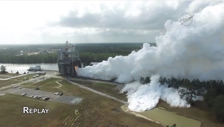
An RS-25 engine throttled up to 113 percent of rated power for the first time in a milestone test-firing on Wednesday. Development Engine 0528 (E0528) was hot fired for about four minutes in the A-1 test stand at the Stennis Space Center in Mississippi to give NASA and prime contractor Aerojet Rocketdyne a first look at how the engine operates at this higher power setting.
The last hot-fire test in a long test series with E0528 is focused on development objectives for hardware that is being delivered from new manufacturing processes as a part of the RS-25 Production Restart Program. Newly built engines will support future Space Launch System (SLS) launches.
In an email, Philip Benefield, Systems and Requirements Team Lead for the SLS Liquid Engines Office, told NASASpaceflight.com that the two primary objectives for this test center around running the engine at the new throttle setting.
“[There are] Two primary objectives: demonstrate engine performance at 113% RPL (Rated Power Level) [and] demonstrate SLM POGO stability and performance at 113% RPL,” he said. “This will be the first test an RS-25 (or SSME) has ever operated at 113% RPL.”
The pogo accumulator assembly is the first of many major engine components that are being manufactured and assembled using newer, more cost-effective processes that will be used to produce new sets of RS-25 engines for future SLS vehicles. NASA and Aerojet Rocketdyne are introducing modern manufacturing methods into the restarted engine production, such as additive manufacturing (also known as “3D printing”).
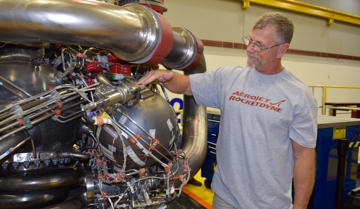
The pogo assembly was manufactured using an AM process called selective laser melting (SLM) that significantly reduced the number of parts needed for assembly and the number of welds.
In addition to the pogo assembly, Benefield also noted: “We have a few redesigned seals installed in a few locations on the engine.
The Stennis test team of personnel from NASA, Aerojet Rocketdyne, and facilities contractor Syncom Space Services (S3) once again took the engine through an event-driven countdown beginning on Wednesday morning. The test started when all of the prerequisite steps prior to ignition were complete and the hardware and the people are ready. Ignition typically occurs in the mid-afternoon Central time. Firing was marked around 14:25 local.
Benefield said that Wednesday’s planned test duration is 260 seconds. During the firing, E0528 will be throttled at 109 percent RPL for 137 seconds, and at 113 percent RPL for 50 seconds. This appeared to go to plan.
To help satisfy objectives for the test, Benefield also noted that the engine was to be started with the liquid oxygen (LOX) conditioned to be colder than normal. The engine uses LOX as its oxidizer and liquid hydrogen (LH2) for its fuel.
Ground testing of the engines over the decades has often “over-tested” the engines to demonstrate that they can operate safely above, below, and beyond conditions that would typically be seen in flight. Testing engines at 113 percent RPL is another example of this over-testing, as newly-built engines are expected to only throttle up to 111 percent RPL during downstream SLS launches.
In contrast to most recent tests, a new engine controller unit (ECU) is not being acceptance tested; instead FM11, the ECU used in the last hot-fire test on February 1, remains integrated with E0528 for this production restart development test.
Hot-fire testing of changes to adapt the RS-25 for SLS use began in January 2015, in the A-1 stand at Stennis. SLS is both physically longer and at times will accelerate faster during launch than Space Shuttles did, requiring different operating conditions for the engines from start through powered flight to shutdown. The four engines in the SLS Core Stage will start and run at higher pressures than the three did in Shuttle, and the hydrolox propellant is also fed to them at colder temperatures.
The single-engine, hot-fire test objectives for certifying the adaptation engine changes were completed at the end of 2017, and the sixteen Shuttle holdover engines will be ready to fly on the first four SLS flights once they each receive a new, test-qualified engine controller. So far, eight ECUs have been acceptance tested, filling out the first two engine sets.
With SSME production long since retired and the need for new engines by the time the fifth SLS Core Stage is being assembled, NASA contracted SSME prime contractor Aerojet Rocketdyne to restart production of the engines for SLS, with cost-reduction goals being a priority. SLS is an expendable launch vehicle, and so some of the design requirements like those for service life are not as high as when the engines flew on Shuttle.
Although new engines will be built using new manufacturing methods, the components will retain the same form, fit, and function as before.
Designed in the 1970s as the Space Shuttle Main Engine (SSME) for the Shuttle Program, the engine’s original rated power level (RPL) of 100 percent was approximately 375,000 pounds of thrust at sea-level and a vacuum thrust of approximately 470,000 pounds. SLS will run the engines at higher thrust levels than Shuttle through most of flight.
At the end of the Shuttle program, the engines were normally operated at 104.5 percent RPL; for SLS, the adaptation engines will run at 109 percent RPL and then 111 percent RPL for the production restart units. The engines are throttleable, and in SLS as with Shuttle they will be throttled depending on in-flight conditions and performance.
Wednesday’s test is the last of four hot-fire tests of E0528 in the Retrofit 1a series for production restart. One of two development engines that are used in most ground testing, E0528 has been in and out of the A-1 stand supporting RS-25 development and certification since 2016. Beginning with a hot-fire in July, 2016, this will be the thirteenth RS-25 test for the engine.
After the test, E0528 will be removed from the A-1 stand and returned to Aerojet Rocketdyne’s Stennis facility for more extensive retrofitting with production restart hardware. Its place will be taken by the other development engine, E0525, for the Retrofit 1b test series planned to begin in August.
E0525 is itself is being retrofitted with new parts to go along with the new pogo accumulator. “E0525 will have [a] redesigned main combustion chamber (MCC) as well as a high pressure fuel pump which incorporates a few production restart changes,” Benefield noted.
In the break, the A-1 test stand will also be modified to enable RS-25 engines to be gimbaled during future hot-fire tests. Although modifications to the A-1 stand will start this year, Benefield noted that gimbaling engines in the stand won’t begin until after E0525 completes its test series and E0528 is back in the stand.
“This [upcoming] rebuild of E0528 will incorporate the redesigned MCC plus redesigned flex ducts which require gimbal demonstration testing,” he added. That “Retrofit 2” test series is currently planned to begin in the late 2019 time-frame.
As with other requirements that changed when going from Shuttle SSMEs to the adaptation and production restart RS-25s, the engines won’t need to gimbal as much in the SLS configuration.
On Shuttle, the maximum gimbal requirement was about ten degrees; for the first four SLS launches with adaptation engines, the requirement is down to eight degrees and for production restart the requirement is six degrees. The capability to swivel or gimbal an engine in the stand while it is firing will allow the design changes for the flex hardware to be fully qualified on the ground.
Quelle: NS
---
Update: 25.02.2018
.
New space telescope expected to make Hubble 'look simple'
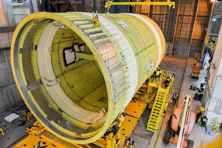
Michoud Assembly Facility on Thursday Feb. 22, 2018 rolled out the latest piece of hardward for NASA's Space Launch System, a 48-foot-high intertank that will connect the rocket's fuel tanks. (Photo by Jude Guidry provided by NASA)
-
Workers at NASA's Michoud Assembly Facility in New Orleans East on Thursday (Feb. 22) rolled out the latest piece of hardware for the nation's new deep-space rocket. Watch the video above to see the piece being shipped out.
The piece, a structural test version of the intertank that will eventually be housed in NASA's Space Launch System, was loaded Thursday morning onto the agency's Pegasus barge. The barge, first used during the Space Shuttle program, will carry the intertank to the Marshall Space Flight Center in Huntsville, Alabama for testing.
The test piece is the second major core stage component built for the Space Launch System at Michoud, dubbed NASA's "rocket factory" for its decades-long role putting together the equipment that has carried astronauts to space. The engine section was delivered in May 2017.
The long-term vision for the 321-foot-tall Space Launch System, or SLS, is a manned mission to Mars, but the goal is to get it and its crew to the Moon first. The SLS will carry astronauts into deep space aboard NASA's Orion spacecraft, which was also built at Michoud and will sit atop the rocket.
At 48 feet high and and 27.6 feet in diameter, the intertank will connect the two giant fuel tanks on the 200-foot-tall core stage and serve as a connection point for the rocket's twin solid rocket boosters. It also houses the avionics and electronics NASA describes as the "brains" of the rocket.
The delivery of the intertank marks "significant progress toward the rocket's first flight," according to a news release.
Quelle: nola
+++
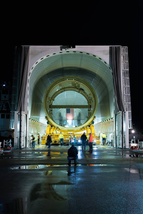
SLS Intertank loaded for shipment, structural testing
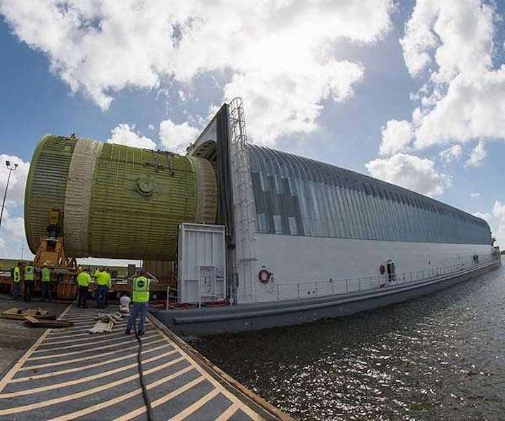
A structural test version of the intertank for NASA's new heavy-lift rocket, the Space Launch System, is loaded onto the barge Pegasus Feb. 22, at NASA's Michoud Assembly Facility in New Orleans.
The intertank is the second piece of structural hardware for the rocket's massive core stage scheduled for delivery to NASA's Marshall Space Flight Center in Huntsville, Alabama, for testing.
Engineers at Marshall will push, pull and bend the intertank with millions of pounds of force to ensure the hardware can withstand the forces of launch and ascent.
The flight version of the intertank will connect the core stage's two colossal fuel tanks, serve as the upper-connection point for the two solid rocket boosters and house the avionics and electronics that will serve as the "brains" of the rocket.
Pegasus, originally used during the Space Shuttle Program, has been redesigned and extended to accommodate the SLS rocket's massive, 212-foot-long core stage - the backbone of the rocket.
The 310-foot-long barge will ferry the flight core stage from Michoud to other NASA centers for tests and launch.
Quelle: SD
+++
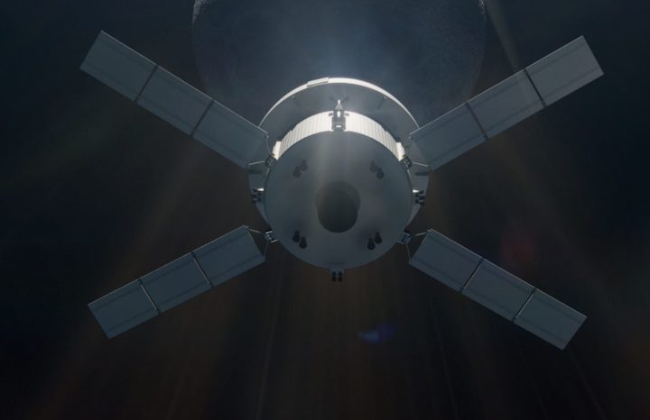
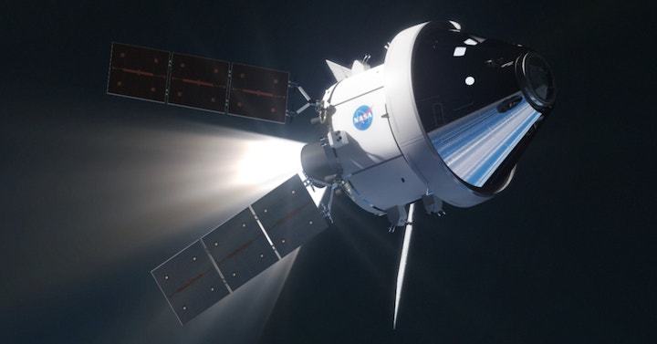
Orion’s Powerhouse
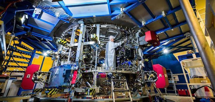
A technician works on the European Service Module that will propel the Orion spacecraft in space and provide air, water and electricity for future crews. ESA, the European Space Agency, and its contractor Airbus Defence & Space are providing the service module for NASA’s first two exploration missions of Orion and the powerful Space Launch System rocket.
The module pictured here will help send Orion about 40,000 miles beyond the Moon during the first integrated test of the spacecraft and rocket and will be delivered to NASA in the coming months. The agencies’ partnership underscores the international cooperation that will extend humanity’s presence to the Moon and beyond.
Quelle: NASA
---
Update: 28.02.2018
.
Orion Crew Access Arm Installed on Mobile Launcher
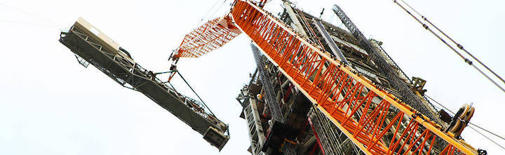
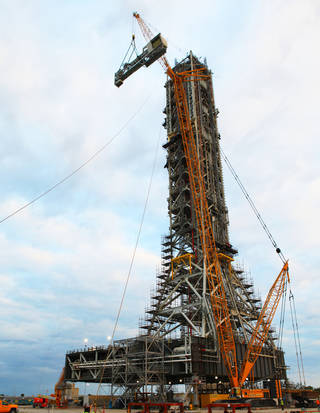
As astronauts prepare for trips to destinations beyond low-Earth orbit, their last steps before boarding an Orion spacecraft will be across a crew access arm on the mobile launcher at NASA's Kennedy Space Center in Florida. This week, the agency reached an important milestone on the path to Exploration Mission-1with the installation of the crew access arm at about the 274-foot level on the mobile launcher tower.
The Exploration Ground Systems team at Kennedy has been overseeing installation of umbilicals and other launch accessories on the 380-foot-tall mobile launcher in preparation for stacking the first launch of the Space Launch System rocket, called the SLS, with an Orion spacecraft. The SLS will be the largest launch vehicle in the world, designed for missions beyond low-Earth orbit carrying crew and cargo to the Moon or beyond. The initial configuration for what SLS can carry past low-Earth orbit and on to the Moon is more than 26 metric tons, with a final configuration of at least 45 metric tons.
The crew access arm installation marks the completion of 17 of the 20 major launch accessories and umbilicals that provide access, power, communication, coolant, fuel and other services to the launch vehicle and spacecraft. The Interim Cryogenic Propulsion Stage Umbilical and a pair of Tail Service Mast Umbilicals are slated for installation in the spring/summer timeframe.
The crew access arm is made up of two major components — the truss assembly and the environmental enclosure, known as "white room." It is given that name not only because is painted white, but also because it is kept clean to avoid contaminants entering the spacecraft prior to flight. The crew access arm is designed to rotate from its retracted position and line up with Orion's crew hatch. The arm will provide entry and emergency egress for astronauts and technicians into and out of the Orion spacecraft.
Although there will be no crew on the first flight, the crew access arm provides a bridge to Orion for personnel and equipment entering the spacecraft and allows the ground crew access for processing and prelaunch integrated testing while in the Vehicle Assembly Building (VAB) and at Launch Pad 39B.
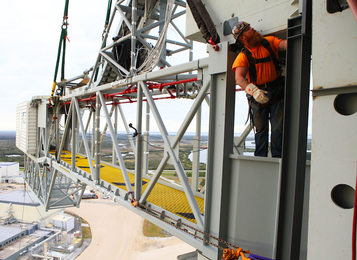
Viewed from the 274-foot level mobile launcher, a technician begins installation of the Orion crew access arm to the tower. The CAA will support the Space launch System rocket at NASA's Kennedy Space Center.
-
After technicians check out the crew access arm and complete the many other ground support equipment installations, the crawler-transporter will move the mobile launcher out to Launch Pad 39B for a fit-check and then inside the VAB for validation and verification tests.
The mobile launcher’s massive steel tower is engineered to withstand the loads of the umbilicals that will connect to the SLS rocket, as well as to endure the natural forces such as wind, temperature, and vibration. Similar to skyscrapers and other large structures, engineers designed the mobile launcher to withstand the movements associated with predicted loads and compensate for anticipated forces. As each piece of hardware is installed, teams precisely measure the structure to ensure the required alignment of the swing arms and umbilicals with the vehicle interface are within the design tolerances.
NASA's Mobile Launcher from a Bird's Eye View
This video provides a bird's eye view of the crew access arm for the Orion spacecraft and Space launch System rocket being attached to the mobile launcher at NASA's Kennedy Space Ceneter in Flirida.
Structural Test Version of the Intertank for NASA's New Deep Space Rocket
A structural test version of the intertank for NASA's new deep-space rocket, the Space Launch System, arrives at NASA’s Marshall Space Flight Center March 4, aboard the barge Pegasus. The intertank is the second piece of structural hardware for the massive SLS core stage built at NASA's Michoud Assembly Facility in New Orleans delivered to Marshall for testing. The structural test article will undergo critical testing as engineers push, pull and bend the hardware with millions of pounds of force to ensure it can withstand the forces of launch and ascent.
The test hardware is structurally identical to the flight version of the intertank that will connect the core stage's two colossal fuel tanks, serve as the upper-connection point for the two solid rocket boosters and house critical avionics and electronics. Pegasus, originally used during the Space Shuttle Program, has been redesigned and extended to accommodate the SLS rocket's massive, 212-foot-long core stage -- the backbone of the rocket. The 310-foot-long barge will ferry the flight core stage from Michoud to other NASA centers for tests and launch.
Quelle: NASA