21.06.2020
EGS begins Artemis 1 launch processing of SLS Booster hardware
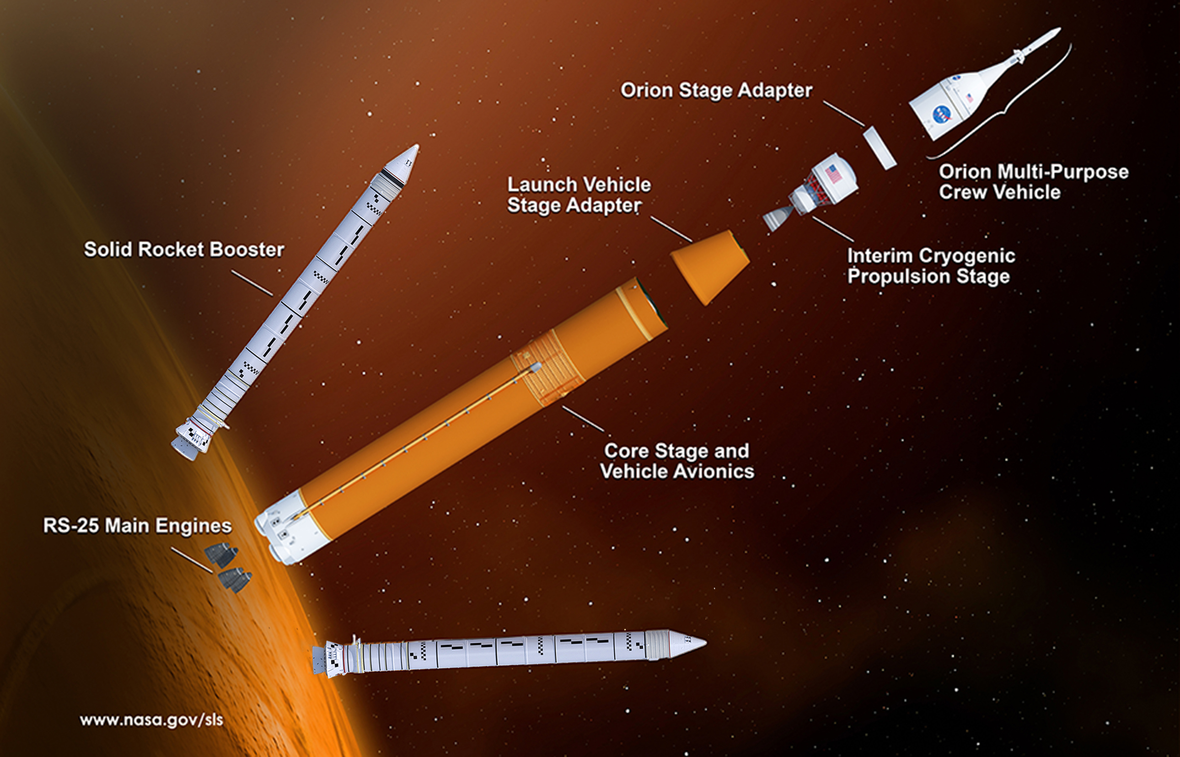
NASA’s Exploration Ground Systems (EGS) program is stepping into the launch processing flow for the Artemis 1 mission after taking delivery of Solid Rocket Booster (SRB) hardware for the Space Launch System (SLS) rocket that will start the uncrewed lunar orbit mission next year.
SLS Booster prime contractor Northrop Grumman turned over almost all of the SRB hardware to EGS in the last week, and all the Booster hardware should be ready to roll into the VAB by the end of the Summer pending plans to re-synchronize their schedules and begin stacking a few weeks after the Core Stage’s Green Run test-firing takes place.
Northrop Grumman delivers Booster hardware to EGS
Artemis 1 launch processing at KSC begins with EGS preparing the boosters in the Rotation Processing and Surge Facility (RPSF) for stacking on Mobile Launcher-1 (ML-1) in the Vehicle Assembly Building (VAB). Stacking operations will wait until the SLS Core Stage completes its hot-fire test later this year at the Stennis Space Center in Mississippi.
A train carrying all ten Northrop Grumman solid rocket motor segments for SLS and two inert segments for the company’s commercial OmegA launch vehicle arrived at Kennedy Space Center on June 15 after reaching the Space Coast on June 12.
“Today was the day that we moved the segments from Jay Jay Yard onto the center,” Jeffrey Angermeier, EGS Flow Director, said in a June 15 interview. “By the end of today, we’ll have all the non aft-segments, eight of those, in its rail car storage site up at Suspect Siding and the two aft motors will be at the Rotation Processing and Surge Facility.”
SLS employs the reusable motor case and booster hardware retained from the Space Shuttle Program. In production facilities around the Salt Lake City area, the empty steel cases were refurbished, refilled with solid propellant, and prepared to fly one more time on the expendable SLS vehicle.
The ten Artemis 1 segments were in storage at Northrop Grumman’s facility in Promontory, Utah, following completion of production a few years ago. For the trip, a special transporter picked up each segment and drove it the approximately 32 km (20 miles) down to a rail yard in Corrine, Utah, where they were put in a transportation container on a rail car.
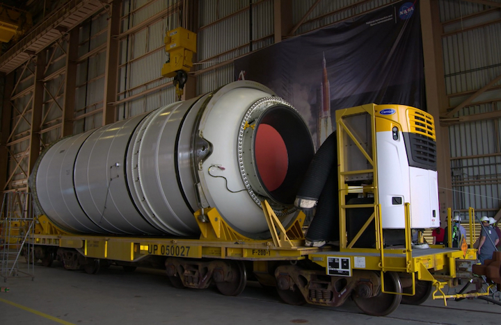
The container for the two aft segments included an air-conditioning unit; Northrop Grumman spokesperson Kay Anderson said in an email that the nozzles in those two segments have temperature requirements to maintain. The train departed Corrine on June 5.
In conjunction with the rail transportation of all the motor segments to NASA EGS, the two booster aft skirts were also officially turned over at KSC last week for launch processing. Northrop Grumman modifies and processes Shuttle forward assembly and aft skirt SRB hardware for SLS at the Booster Fabrication Facility at KSC.
Each aft skirt houses thrust vector control (TVC) hardware that receives steering commands routed from the SLS flight computers up at the top of the Core Stage and gimbals the booster nozzle via hydraulic rock and tilt actuators. Two redundant hydraulic power units (HPU) in each aft skirt provide the power to the actuators to move the nozzle.
The combined Orion/SLS Artemis 1 vehicle will end up sitting on the aft skirts when stacking is finished, with each skirt positioned over four vehicle support posts (VSP) on the Mobile Launcher. A set of smaller solid rocket motors are mounted on the outside of the skirts to help push the boosters away two minutes into flight when they are separated from the rest of the vehicle after burn out.

Credit: Northrop Grumman.
(Photo Caption: A specialized transporter carries one of the aft segments the approximately 32 km (20 miles) from Northrop Grumman’s Promontory, Utah, production facility to Corrine, Utah, where the segment was placed on the train for shipment to Florida. The transporter is used to move segments on-site at Promontory during different phases of production. Once loaded with solid-fuel, each of the ten SLS motor segments weigh on average about 300,000 pounds, which is significantly heavier than the much larger Core Stage of the vehicle, albeit when the liquid-propellant stage is unfueled.)
The refurbished aft skirt structures were transported from Hangar AF at Cape Canaveral to the BFF in September 2016 to begin modification and integration work. As with the motor cases, both units are Shuttle veterans. Anderson noted that the left-hand aft skirt flew on eleven Shuttle launches while the right-hand one flew on nine launches.
Additional structural reinforcements were added to the skirts in the BFF to handle the heavier SLS vehicle, along with installation of thermal protection, the TVC and booster separation motor (BSM) systems, electrical wiring harnesses, and development flight instrumentation. One of the last operations was an acceptance test, where the skirt’s hydraulic TVC systems were loaded with hydraulic fluid and hydrazine fuel for the HPU and run through a full duty cycle.
“The left Aft Skirt Assembly completed Acceptance Check-out (ACO) testing in November 2019, and the right Aft Skirt Assembly completed in February 2020,” Anderson said. “The left Aft Skirt Assembly was completed in March, [and the right one in May].”
The aft skirt assemblies were stored at the BFF until NASA was ready to receive the propellant segments from Utah. With the train en route, the aft skirts were taken out of storage and covered up on June 9 for the drive from the BFF to the RPSF the next day.

Credit: NASA/Ben Smegelsky.
(Photo Caption: The two Artemis 1 SLS booster aft skirts in the Booster Fabrication Facility on June 9 just ahead of delivery from Northrop Grumman to the EGS program for launch processing. Delivery was synchronized with the rail shipment of the booster motor segments from Utah. The left-hand aft skirt is in the foreground, the right-hand in the background. Six TVC system servicing ports can be seen on both, along with the aft booster separation motors (BSM) on the right-hand unit.)
The RPSF includes four buildings in an area just north of the VAB outside the crawler-transporter tracks: the Rotation/Processing Building (RPB), two Surge buildings (garages for storing motor segments inspected and ready for stacking) and a support building .
The work to prep the segments for stacking is performed in the RPB. “If you think about the footprint in the rotation building, there are kind of four permanent structures that we have,” Angermeier explained.
“We have what we call two aft booster assembly build up stands, and we also have what we call two inspection stands. Then we have a series of pedestals that we use for some inspections right after we take it off the railcar.”
“The aft booster assembly build up stands is where we preposition the aft skirt, [and] we then mate the aft segment to the skirt. And [then] we go through a series of operations to make it the aft booster assembly [because we have things to install things] like the Core Stage attach ring, we have some DFI that we need to install, we have cable harnesses we need to run, and thermal curtain installation on the bottom of the aft skirt,” he added.
“All the other segments, they come off the railcar and go over to that pedestal I mentioned before. There’s a few operations that we do on the pedestal, and then we lift it and we put the segment on top of a pallet that’s in what we call one of two inspection stands.”
Center and forward segments will be stored in the nearby Surge buildings of the RPSF until it is their turn for stacking in the VAB.

Credit: NASA/Ben Smegelsky.
(Photo Caption: One of the aft skirts is rolled into the Rotation/Processing Building of the RPSF on June 10 when both were delivered from Northrop Grumman to EGS. Each one will be loaded into a build-up stand in the building where they will be connected to an aft motor segment and exit cone. Additional hardware such as the Core Stage Attach ring, electrical harnesses, and instrumentation will also be installed before the assembly is ready to stack on the Mobile Launcher.)
Angermeier said that EGS was moving directly into work to build the aft assemblies for stacking beginning with the left booster. After arriving from the BFF, the aft skirts were set up in the build-up stands. The left aft segment is the first offload planned from its rail car.
“Our plan is to get into the mate with the aft skirts [the week of delivery], and so we’re going to start with the left aft segment and we’re going to get right into the offload operations,” he said.
The forward assemblies that will be placed on top the completed booster stack in the VAB are also ready in the BFF. “All assembly operations are complete for both Forward Assemblies; final closeout inspections are underway,” Anderson said. “Final structure mates occurred in December 2019 (left) and February 2020 (right). Acceptance check-out for the Forward Assemblies were completed in March (left) and April (right).”
The forward assemblies consist of a forward skirt where the top of the boosters attach to the Core Stage’s intertank, a frustum, and a nose cap. The forward skirt also houses most of the Booster avionics boxes.
“The general agreement that we have with the Booster element is that we would like [the forward assemblies] turned over about the time that we start stacking the boosters in the Vehicle Assembly Building,” Angermeier noted. “They are making progress on those forward assemblies, and we will agree on a final turnover date with them as we mature the start of our booster stack schedule.”
Artemis 1 integration schedule dependent on Core Stage hot-fire
The aft assemblies will be completed in the RPSF, and the rest of the segments will be inspected and stored, ready for stacking. “We’ll keep [the aft booster assemblies] in the build up stands until we need those over in the VAB once we commit to stacking,” Angermeier said.
When EGS can commit to stacking hinges on the Core Stage hot-fire test. The test-firing of first SLS Core will culminate the Stage Green Run test campaign in the B-2 Stand at Stennis. And most of the launch processing flow is dependent on when that occurs.

Credit: NASA/Ben Smegelsky.
(Photo Caption: The completed aft skirts (left) and nearly-completed forward assemblies (right) for Artemis 1 in the BFF on June 9. Final closeouts on the forward assemblies are one of the last tasks remaining before they are ready to stack. They will stay in the BFF until booster stacking in the VAB begins. In between is a frustum being prepared for Artemis 2.)
“We’re not going to start stacking the boosters until after Core Stage hot-fire, and we’re working with Core Stage to understand how long after that they will deliver the Core Stage to us,” Angermeier said. “Our goal is to probably start stacking segments two to four weeks after hot-fire.”
“We think we have about a month of work that we have to do on that stacking, but we are protecting about a month contingency in case we have any first flow issues that we have to deal with that might take a little bit longer.”
Similarly, work on the Artemis 1 Orion spacecraft in the Armstrong Operations and Checkout Building reached a holding point, and forward work will be re-synchronized after the Core Stage test-firing.
Hands-on Green Run activities were suspended in mid-March due to the coronavirus pandemic. The stage is outdoors at Stennis and work was again interrupted for several days ahead of powering up the stage in the stand due to the passage of Tropical Storm Cristobal in early June.
Continued COVID-19 work capacity restrictions, more possible weather interruptions, and unknowns with first-time operations leave uncertainty in the timing of the hot-fire test. Currently, it is forecast in the autumn with the Core Stage being delivered by barge to KSC around the end of the year.
EGS wants to be in a position to stack the Core Stage to the Boosters when it arrives at Kennedy. “Our goal is to not start stacking too early because we don’t want start it before Core Stage hot-fire but we don’t want to wait too late because the last thing we ever want is for the Core Stage to be here ready to be stacked and our boosters aren’t ready,” Angermeier noted.
“So we think we found that sweet spot, that two to four weeks after the hot-fire [is when] we’ll commence stacking the segments on the Mobile Launcher.”

Credit: NASA/Bill White.
(Photo Caption: One of the coverings is removed from the nozzle of an aft segment in the Rotation/Processing Building on June 16. The segment is still sitting in the rail car with the air-conditioning unit that was used during transportation from Utah. The segment will eventually be lifted off the car and rotated to vertical. Following initial inspections, it will then be mated to its aft skirt in one of the build up stands in the building.)
One of the reasons that the EGS and SLS Programs don’t want to stack the boosters early is a time limit carried over from the Shuttle-era on how long they can stand that way. The stacked boosters have an approximately 12-month life limit, so once they are built up on the Mobile Launcher, NASA has about a year to launch Artemis 1 before they would need disassembly, inspection, and possible maintenance.
“Field Joint J-leg function and proper contact is the primary reason we have the 12 month stack life requirement,” Anderson said in an email. “The J-leg is a redundant sealing feature in the motor field joint molded into the insulation that depends on contact with the adjacent segment to create a seal when pressurized.”
After the Core Stage arrives at KSC and joins the Boosters on Mobile Launcher-1 in High Bay 3 of the VAB, the outline of work is similar to the preview EGS detailed back in 2018, including some work (like main engine refurbishment) that was originally planned to take place at Stennis but can be more efficiently carried out in parallel with other work once the Core arrives at KSC.
In addition to some of the Core Stage RS-25 engine refurbishment work deferred from Stennis to KSC, the Partial Stack Modal Test was deleted from Artemis 1 integration activities to shorten the schedule, leaving one Integrated Modal Test (IMT) in the processing flow in the VAB.

Credit: NASA/Bill White.
(Photo Caption: The other cover is removed from the top of an aft motor segment in the RPB on June 16. EGS hopes to mate the first aft segment to its aft skirt sometime next week. In the background, one of the booster exit cones sits inside an environmental enclosure. Following the aft-segment-to-aft skirt mate in one of the build-up stands, the exit cone will be attached to the nozzle of the segment, along with mating to the two TVC actuators in the skirt.)
“Once we stack Core Stage in the integration cell, we essentially kick off three critical paths,” Angermeier explained. “One is all the preparations for the Integrated Modal Test.”
“The second one is we stack all the remaining elements of the vehicle, the LVSA (Launch Vehicle Stage Adapter), the ICPS (Interim Cryogenic Propulsion Stage), and the OSA (Orion Stage Adapter). We also have the Orion simulator that we are going to stack first as we want to use the simulator for the Integrated Modal Test.”
“The third critical path is the accomplishment of the deferred work from Stennis,” he added.
Following the IMT, the simulator will be removed and the Orion launch stack will be brought in and connected on top of the OSA.
Besides the Core Stage, the only other hardware element that hasn’t yet reached the launch site is the conical LVSA which connects the Core Stage to the ICPS. The approximately thirty-foot tall connector was assembled and outfitted by prime contractor Teledyne Brown Engineering at the SLS Program’s home at Marshall Space Flight Center (MSFC) in Huntsville, Alabama.
NASA’s Pegasus barge will carry the LVSA from MSFC to KSC this summer. “Right now we’re expecting that to arrive on barge in the late-July, early-August timeframe,” Angermeier said.
“We’re working with the SLS Program on the exact arrival date. We’ll store that in High Bay 4 off to the side.”

Credit: NASA/Glenn Benson.
(Photo Caption: NASA EGS and Jacobs technicians practice segment lifting and field joint mating operations with inert hardware in VAB High Bay 4 in January. On the left, an inert center segment is lifted to practice mating its bottom, clevis end to the top, tang end of an empty, bare metal segment case. On the right, another bare metal cylinder is mated to an inert aft assembly in one of the build up stands used early in the Shuttle program. Shuttle SRBs were prepared for stacking in the VAB in the late 1970s and early 1980s before the RPSF was built.)
Other work that EGS looks to complete this Summer ahead of stacking the booster on ML-1 is to finish the last phase of practice with inert test hardware. EGS has been using one inert aft booster assembly and one inert center segment for practice sessions for a couple of years and with ML-1 preps nearly complete, they will run through the procedures on the Mobile Launcher’s support posts and the multi-level work platforms installed in VAB High Bay 3.
“We have about two weeks of operations practicing stacking,” Angermeier said. “They have been practicing a lot of the joint mating activities offline in High Bay 4 with one of the stands that we have over there. Our plan to stack it on the ML is to occur in August.”
Quelle: NS
----
Update: 26.06.2020
.
SLS Testing Continues for NASA's First Artemis Moon Mission
While a pandemic and social unrest have swept the nation, NASA is staying focused on their goal of returning America to the moon with the Artemis missions. Recently, the two solid rocket boosters for the agency’s giant Space Launch System (SLS) rocket were shipped to Kennedy Space Center in Florida, while engineers at Stennis Space Center in southern Mississippi continue putting the core stage through a series of ‘Green Run’ tests which will continue throughout the summer and culminate with a full-duration 8-minute test fire of the mammoth rocket later this year.
“Green Run is the step-by-step testing & analysis of the new SLS rocket core stage that will send astronauts to the Moon,” said Richard Sheppard, the SLS Stages Green Run Test Lead from NASA’s Marshall Space Flight Center in Huntsville, Alabama. “This testing will reduce risks for, not only the first flight, but also for the Artemis mission that will land astronauts on the Moon in 2024.”
Work with the rocket at Stennis began in January, but was temporarily suspended when Stennis went to Stage 4 on NASA’s ‘Agency Response Framework’ in response to a rise in COVID-19 cases across the region (Stennis is not far from New Orleans, which saw an explosion of COVID-19 this spring).
The ‘Green Run’ test campaign is actually a series of eight different tests, the first of which was completed before Stennis halted work due to the pandemic. Known as the modal test, teams used shakers to, “impart dynamic forces on the suspended stage to identify primary bending modes of the stage. Information from the modal test will help engineers verify vehicle models needed for the operation of the rocket’s guidance, navigation and control systems,” according to NASA.
Now, the booster is undergoing its second test series, which will test its avionics and three computers that control the giant rocket’s flight as it soars away from KSC pad 39B and into space with the Orion crew module. Engineers designed software similar to the flight software for Green Run, and a special stage controller will be used to simulate the Launch Control Center operations that will control the actual launch.
“The core stage avionics along with Green Run software have successfully completed tests in our test laboratories at Marshall,” said Lisa Espy, the core stage avionics lead at Marshall. “I am excited to see the flight systems come to life that will control the rocket as it sends the first Artemis mission to the Moon.”
Here is a summary from NASA of the eight tests for the 212-foot-tall SLS core stage that make up the ‘Green Run’ test campaign:
- Test 1- Modal Test: The first test in the Green Run series, a modal test was conducted in January. This test used shakers to impart dynamic forces on the suspended stage to identify primary bending modes of the stage. Information from the modal test will help engineers verify vehicle models needed for the operation of the rocket’s guidance, navigation and control systems.
- Test 2- Avionics: The rocket’s avionics, which are distributed throughout the stage, will be turned on and checkout out. This includes not only flight computers and electronics that control the rocket but also those that collect flight data and monitor the overall health of the core stage.
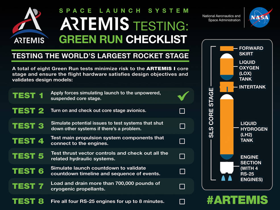
- Test 3- Fail-Safes: Engineers will check out all the safety systems that shut down operations during testing. To do this, they will simulate potential issues.
- Test 4- Propulsion: This will be the first test of each of the main propulsion system components that connect to the engines. Command and control operations will be verified, and the core stage will be checked for leaks in fluid or gas.
- Test 5- Thrust Vector Controls: Engineers will ensure that the thrust vector control system can move the four engines and check all the related hydraulic systems.
- Test 6- Countdown: This test simulates the launch countdown, including step-by-step fueling procedures. Core stage avionics are powered on, and propellant loading and pressurization are simulated. The test team will exercise and validate the countdown timeline and sequence of events.
- Test Case 7- “Wet” Dress Rehearsal: Engineers will demonstrate loading, controlling and draining more than 700,000 gallons of cryogenic propellants into the two test stand run tanks and then returning the stage to a safe condition.
- Test Case 8- Hot Fire: The core stage’s four RS-25 engines will operated for up to 8 minutes, generating 1.6 million pounds of thrust, the amount of thrust the engines produce at sea level on the launch pad at liftoff.
SLS is the largest rocket stage NASA has ever produced, which will hold the cryogenic liquid hydrogen and liquid oxygen tanks that will feed its four RS-25 rocket engines. The ‘Green Run’ test campaign will help validate the core stage design and confirm that the hardware is ready to ship to KSC in Florida for flight.
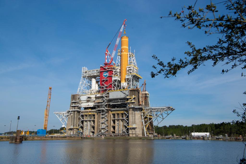
The next time it is fueled and the engines lit, will be when SLS launches Orion to the moon on the Artemis-1 mission.
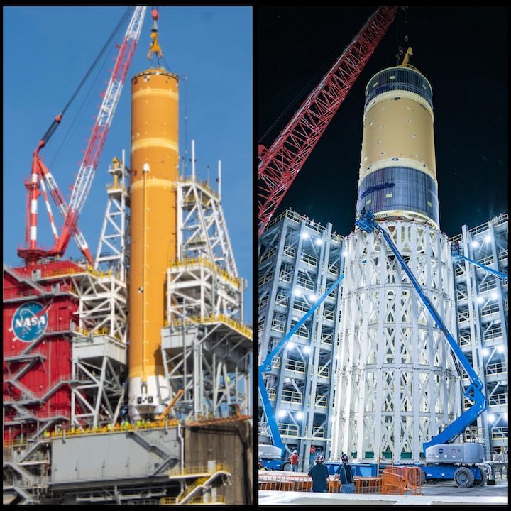
Meanwhile, at Marshall Space Flight Center in Huntsville, Alabama, engineers are wrapping up a 3-year structural qualification test series with one upcoming final test that will push the design for the rocket’s liquid oxygen tank to its limits by intentionally trying to break it. Hydraulic systems will apply millions of pounds of force to push, pull and bend it to see just how much pressure the tank can take, simulating forces the tank will experience during launch and ascent. Except instead of being full of liquid oxygen propellant, it will instead be full of water.
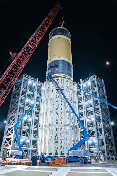
“We take rocket tanks to extreme limits and break them because pushing systems to the point of failure gives us data to help us build rockets more intelligently,” said Neil Otte, chief engineer for the SLS Stages Office at Marshall. “Breaking the propellant tank today on Earth will provide us with valuable data for safely and efficiently flying SLS on the Artemis missions to the Moon.”
“The tank is fitted with thousands of sensors to measure stress, pressure and temperature, while high-speed cameras and microphones capture every moment to identify buckling or cracking in the cylindrical tank wall,” says NASA. “This final test will apply controlled forces stronger than those engineers expect the tank to endure during flight.”
Structural testing has already been completed on three of the rocket’s largest core stage structures: the engine section, the intertank, and the liquid hydrogen tank.
“The liquid oxygen tests and the other tests to find the point of failure really put the hardware through the paces,” said April Potter, the SLS test project manager for liquid oxygen and liquid hydrogen structural tests. “NASA will now have the information to build upon our systems and push exploration farther than ever before.”
Quelle: AS

