
14.03.2021
NASA, Boeing approaching first major join of second SLS Core Stage
Operations for the first major join of the main elements of the second Space Launch System (SLS) Core Stage are expected to begin later in March as NASA and prime contractor Boeing work to deliver the stage in 2022 for the Artemis 2 launch.
The three elements that compose the top half of the rocket, the forward skirt, the liquid oxygen tank, and the intertank, are finishing up standalone integration and testing at the Michoud Assembly Facility (MAF) in New Orleans in preparation for being stacked in the factory’s Vertical Assembly Building.
While the top half of the rocket stage is being put together in the Spring, production and assembly also continues on the bottom two elements. Major hydraulic and pneumatic parts of the Main Propulsion System are being installed inside the engine section ,and Boeing completed spraying primer on the outside of the liquid hydrogen tank after issues during initial attempts.
Getting ready for forward join stacking
Core Stage prime contractor Boeing is in the middle of production of the second vehicle for NASA at the East New Orleans historic Michoud facility. At a high level, assembly starts with welding aluminum structural panels into barrels and domes; the full structure of the big pieces of the rocket are then welded and bolted together, followed by an integration phase were they are outfitted with their working systems.
Outfitting of the five primary elements — the forward skirt, liquid oxygen (LOX) tank, intertank, liquid hydrogen (LH2) tank, and engine section — is done separately. In contrast to the interior of the two large propellant tanks, which are mostly empty so they can be filled with the cryogenic liquid rocket fuel, the insides of the other three “dry” elements are lined and/or filled with computers, gyroscopes, batteries, wiring, instrumentation, propellant plumbing, and other fluid systems.
Once the elements finish their standalone integration, Boeing starts putting them together, beginning with the top three elements in what is called the “forward join” or “major join 1.” The forward skirt, LOX tank, and intertank are stacked vertically first; then, after being rotated into a horizontal orientation, the LH2 tank and the engine section are attached one at a time.

Credit: NASA/Eric Bordelon.
(Photo Caption: The Core Stage-2 intertank in its new integration area at MAF in September 2020. Integration, or outfitting, of the intertank and forward skirt are being moved to adjacent areas on the east side of the Building 103 floor to accommodate future expanded Core Stage production.)
Forward join operations for the second Core Stage flight article, Core Stage-2, are expected to start later this month with the top three pieces of the rocket nearing readiness to be bolted together. The two dry elements, the forward skirt and the intertank, are fully outfitted; the intertank recently concluded its standalone functional testing suite.
“They did their [intertank] break of configuration [review], so we are complete with functional test,” Ben Birkenstock, NASA’s Manufacturing and Production Lead for the SLS Stages Office, said in February 25 interview. “Test case six was the last one that we got done last week.”
A break of configuration review is held to confirm that all the required data was collected during functional testing before disconnecting test equipment and reconfiguring the flight hardware. “The next step [is] some closeout production work, so they’re doing system tunnel brackets, they’re doing some TPS [Thermal Protection System] pours that you couldn’t get done while the testing was going on,” Birkenstock noted.
“This is looking to go into major join in the middle of March.”
Additional outfitting of passive systems like purge duct installations was also in work on the intertank after functional testing was completed.
After the forward skirt and intertank panels were assembled a few years ago, the metallic structures were fully coated with corrosion-protecting primer before spray-on foam insulation (SOFI) was applied to their exterior surfaces. The next phase of production was the standalone integration they are wrapping up now; the elements were set up in dedicated work areas where miles of wiring harnesses were installed, routed, and secured to bracketry and shelves inside.
The wiring was tested to ensure it was working from end to end as operational and development flight instrumentation was installed along with the computers and avionics equipment. The three flight computers that fly the SLS vehicle during launch are located in the forward skirt while the vehicle batteries and one of the rate gyro assemblies (RGA) are located in the intertank; after all the electronic equipment was installed, standalone functional testing was performed on the elements.
The forward skirt completed its functional testing in late 2020 and is waiting to be mated on top of the LOX tank when it gets the call.
To assemble the top three elements, the intertank will be moved into the vertical integration cell first. When it is ready, currently scheduled for mid-March, it will be rolled from its integration area on the east side of Building 103 across the floor into the adjoining Building 110. In Building 110, also known as the Vertical Assembly Building at MAF, the intertank will be lifted into Cell D.
Once in Cell D, the intertank will be ready for mating with the LOX tank, which is currently going through the latest round of horizontal outfitting in Area 47/48 of Building 103, the final assembly area.
The LOX tank has received its exterior applications of primer and TPS foam in the production cells of nearby Building 131. The sump was recently installed at the bottom of the tank, which is where the two large feedlines will eventually connect to deliver the oxidizer from the tank down to the four RS-25 engines that will eventually be installed in the bottom of the stage.
“We were able to get the LOX sump on in the vertical, and then we broke it over and brought it in here [final assembly] for final closeouts,” Birkenstock noted.
“That [work] scope includes the sensor mast internal install as well as the [tank] covers, and then we’ve got some sensor islands and some instrumentation around the outside that we’ve got to install before we go put it on top of the intertank.”

Credit: NASA/Michael DeMocker.
(Photo Caption: The LOX tank for Core Stage-2 is rolled into Building 110 in November 2020. At this point, the tank had just finished receiving its SOFI in Cell N of the adjacent Building 131 and was moving into Cell A in Building 110 for additional outfitting in a vertical orientation.)
The internal sensor mast assembly has the liquid level sensors used by vehicle and ground system computers to determine how much cryogenic propellant is in the tank. Both propellant tanks on the first two Core Stages are dotted on the outside with development flight instrumentation (DFI) sensors to collect data on in-flight environments. The sensor packages slightly protrude beyond the outer mold-line (OML) of the vehicle and are surrounded by streamlined, circular islands of TPS foam.
These local areas on the exterior of the tanks were sealed off during the full-scale foam sprays to remain accessible, but now the sensors will be installed and then the TPS foam islands will be added. Additional TPS closeouts will also be done on the recently-installed sump on the aft end of the LOX tank before it is ready for mating to the intertank.
Once the interior is configured, the cover on the forward end of the tank will be installed and the vehicle’s redundant inertial navigation unit (RINU) will also be mounted in its flight position on the forward cover.
Core Stage-2 is forecast to be completed in mid-2022 and is assigned to help launch the Artemis 2 Orion lunar mission, which will be the first crewed flight of both SLS and Orion.
Engine section integration critical path
The most complicated piece of the complicated rocket is the engine section; when finished, it will include avionics, wiring, sensors, propellant feedlines and valves, hydraulic systems, and other equipment that constitutes the majority of the Core Stage’s Main Propulsion System (MPS). Like the first engine section, the Core Stage-2 element will include over 150 wire harnesses, which have to be routed and clamped across the long wiring runs.
Over 5,000 clamps hold the wiring runs inside the engine section in place, and once those are laid out and secured, they will go through continuity and potential tests to make sure all the copper and the insulation of the wiring are still healthy. In addition, hundreds of sensors and test instrumentation will be spliced into the wiring.
Along with the wiring installations, hundreds of orbital tube welds are being done to connect the different MPS fluid systems, from propellant lines to hydraulics to pneumatics. A couple of the larger engine section subsystems that are first assembled and processed “offline” outside the volume — the thrust vector control (TVC) platforms and the large gaseous helium composite overwrapped pressure vessels (COPV) — are now being completed for subsequent installation.
“TVC platforms got flown in this week and last,” Birkenstock said. “Helium tanks have not [been installed] yet; we’re still working [preparations for] that.”
The TVC platforms, one for each of the vehicle’s four hydraulic systems, are installed on top of the thrust structure that is positioned near the bottom of the engine section barrel. “We’ve gotten three out the four over there,” he noted. “They finished their high-pressure helium leaks checks [on March 4th], and so that’ll go into the barrel.”
Each TVC platform holds most of the equipment for the hydraulic system, including the auxiliary power unit, hydraulic accumulators, reservoir, filter manifold, and circulation pump. When fully outfitted, the engine section will have five helium COPVs installed inside.
“We had to reconfigure the [work] platforms and the tooling in there to open up some more work, so that’s part of what they were doing was bringing online new, more robust [work] platforms inside [the engine section] so you could have more people [safely] working,” Birkenstock said.
Birkenstock also noted that the current forecast is for standalone engine section integration to be completed around the end Summer 2021. When complete, the element will be transported and installed in Cell A in Building 110 where it will be bolted together with the boattail assembly.

Credit: NASA/Steven Seipel.
(Photo Caption: In the foreground, the boattail assembly, and in the background the engine section for Core Stage-2 on March 5 at MAF. Standalone work on the boattail extension and base heatshield was recently completed and the structure was moved from across the aisle where the engine section is to this location. NASA and Boeing are reworking the floor plan at MAF to expand Core Stage production, particularly future engine section builds.)
The boattail is a short extension and fairing bolted to the bottom of the engine section that includes the locations of exhaust ports and access panels for some of the equipment inside. It also is the base heatshield for the stage where different thermal protection system (TPS) elements are attached, such as the engine mounted heat shield (EMHS) blankets that protect the powerheads of the four RS-25 engines.
“Boattail is done, that work scope is done,” Birkenstock said. “It’s ready to be integrated and we’ve got cork on the outside. They’ve actually finished out that work scope, so it’s ready and that’s just waiting for the integration.”
Boeing and NASA are incorporating lessons into assembly and integration of the second engine section build from the long learning curve of the first one. Birkenstock said the production work is going more efficiently this time and so far has not required extensive, around-the-clock shifts.
“It’s eased a little bit, but it’s going to pick up again,” he said. “When we’ve got delivery of critical parts, we will ramp up and surge accordingly. So if we got a TVC platform that we want to get in that opens up a bunch of job kits, we’ll work really hard to get that [done] and then that opens up a bunch more work scope that we can go work through at a regular pace. We haven’t gone 24/7 yet on anything, but at some point we’ve got that knob to turn if it comes to it.”
One of the watch items that a year of living with a pandemic increased attention on was the parts supply chain. “We’re still fighting parts being delivered on-time,” Birkenstock said.
“Part of that is the supply chain all has different, varying levels of COVID effects and how they’re dealing with it. We’ve gone from the extreme of companies shutting down and not letting anyone else in to somewhat making their marks and the whole gamut in between.”

Credit: NASA/Jared Lyons.
(Photo Caption: The Core Stage-2 forward skirt (foreground, right) is prepared for lifting out of Area 15 at MAF on February 19, with the recently-welded barrel of the Core Stage-3 engine section (middle) and the Core Stage-2 engine section in its integration area (left) looking on. Engine section integration will be taking over this area, and the forward skirt move was done to allow the blue pedestals and forward skirt tooling to be relocated to the east side of the building.)
“I’ll say the Core Stage-2 sparing strategy hasn’t in general changed; it’s more of a day-to-day how do we [adjust],” he added.
After standalone engine section integration is completed and the engine section and boattail are bolted together, an additional set of connections and orbital tube welds will be made in preparation for full functional testing — following which the engine section/boattail assembly will be ready to be mated horizontally to the rest of the rocket.
LH2 tank primer spray retry completed
In late-February, the LH2 tank was still in Cell P of Building 131 where a second round of primer sprays on the metal skin of the tank structure was being completed. The tank was in Cell P longer than expected because the first attempts to apply the corrosion-protecting primer did not meet requirements.
“The first couple attempts at getting the primer on this time around didn’t go so well, so we had to figure out ‘do we strip it all off or do we just take parts [off],'” Birkenstock said. “It was failing its checkout requirements after the priming operation.”
After the primer is sprayed on and dries, they test the robotic paint job by putting tape on top of the coat of primer paint and watching what happens when the tape is pulled off. “It’s got a post-prime lift-off tape test that they do, and so if you spray the paint on and it comes off [with the tape], that’s not good,” he said.
After stripping the primer off, reviewing what happened, and correcting issues found with the process, the LH2 tank team was ready to try again. Birkenstock said the issue was with the process of preparing the tank surface for the spray, not necessarily with the procedures to apply the primer.

Credit: NASA/Jared Lyons.
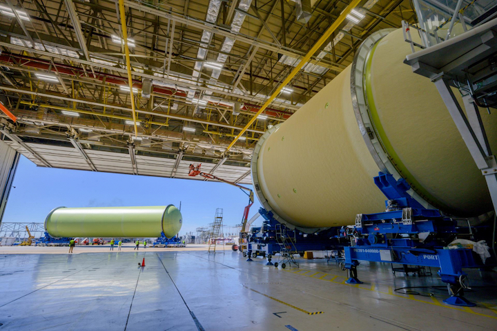
(Photo Caption: The Core Stage-2 LH2 tank is backed out of Cell P in Building 131 on March 3 following completion of primer sprays. The primer application was completed after initial attempts were unsuccessful; the tank was moved into the final assembly area in Building 103 nearby for additional outfitting and preparations to return to Building 131 for foam sprays in Cell N.)
“We made them take it all off from the first attempt. We did a robust RCCA, root cause corrective action, and had the output from that as a gate before we let them spray again,” he noted. “They were having issues with the surface prep before they sprayed and making sure that it would work with that process. So we worked through that, implemented some corrective actions, and we’re doing well the second time around.”
The final primer sprays were completed on February 25, and on March 3 the LH2 tank was moved out of Cell P and over to the final assembly area in Cell N in Building 103 for preparation for foam sprays of the barrel section and the domes on both ends.
“They’ve got some additional outfitting that they’ll do before it goes into [Cell] N,” Birkenstock said. “They’ve got to get some sensor runs on, those kind of things, and then it’ll go get its foam.”
Following the foam sprays and trimmings, the LH2 tank will return to the final assembly area of Building 103 for additional outfitting of hardware, such as the brackets and fittings for the two liquid oxygen feedlines that are attached to the exterior of the tank. The tank will subsequently be mated with the forward join to form the upper four-fifths of the rocket.