
22.02.2019
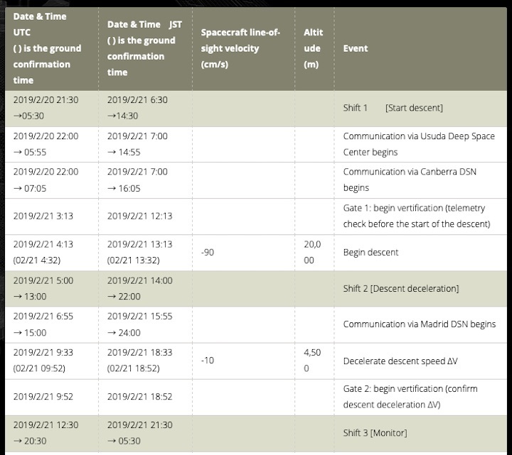
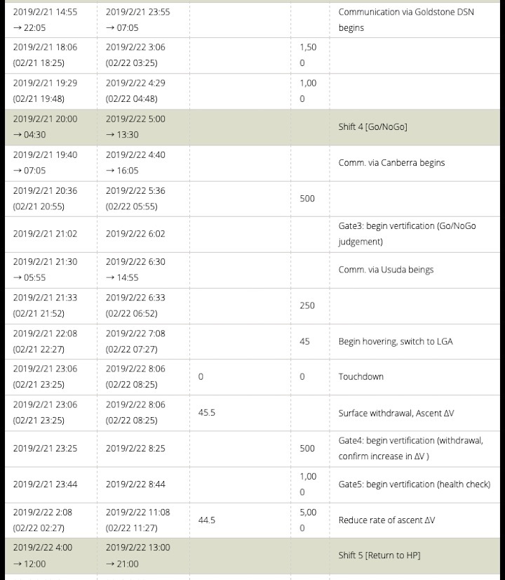
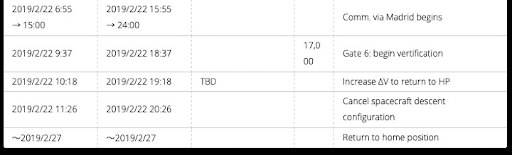
TD1-L08E1 operation schedule
Notes:
- Time: Approximate scheduled time. UTC is Universal Time, JST is Japan standard time. There is a possibility that this may change during operation.
- Spacecraft speed: This is the speed along the line-of-sight relative to the asteroid (minus is towards the asteroid, positive is away). Numerical value is displayed only when speed control is performed. After a speed control operation, the speed changes due to the gravitational force of Ryugu and other celestial bodies.
- Altitude: Approximate distance from the surface of Ryugu
Schematic of the TD1-L08E1 operation
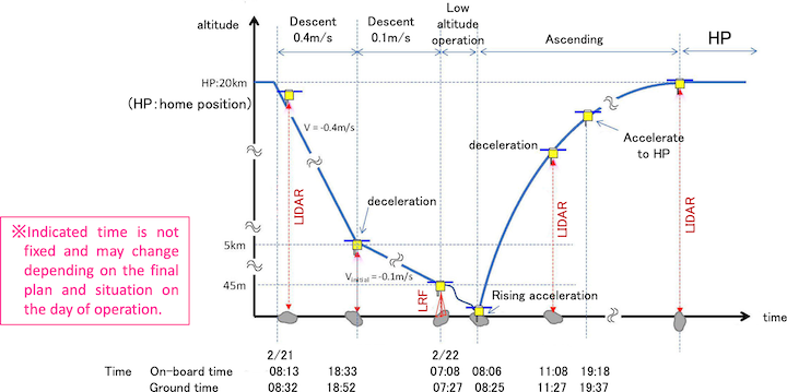
- Fig.1 Schematic of the TD1-L08E1 operation
TD1-L08E1 low altitude sequence
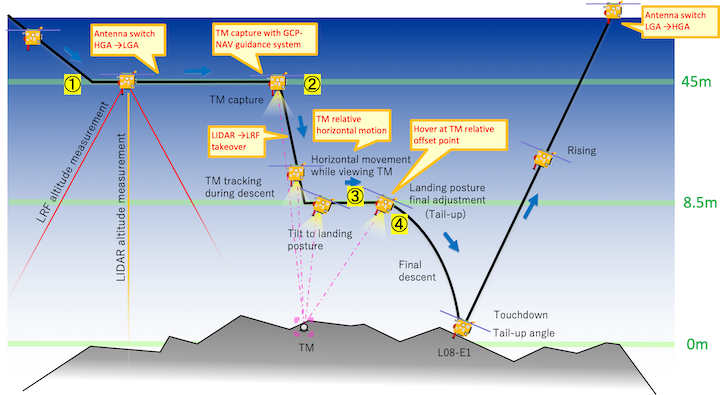
- Fig.2 TD1-L08E1 low altitude sequence
Hayabusa2 project
2019.02.21
+++
Topics
The touchdown site
Up until now, the Hayabusa2 mission has progressed smoothly. One particular success was the landing of the small rovers on the surface of Ryugu, which could not be achieved during the first Hayabusa mission. Now on February 22, 2019, we plan to touchdown on the asteroid surface; another challenge that did not go as expected for Hayabusa.
Our original schedule planned for touchdown in late October of last year (2018). However, Ryugu was revealed as a boulder strewn landscape that extended across the entire surface, with no flat or wide-open regions. Before arriving at Ryugu, it was assumed there would be flat areas around 100 meters in size. But far than finding this, we have not even seen flat planes 30 meters across!
During the scheduled time for touchdown in late October, we did not touchdown but descended and dropped a target marker near the intended landing site. We were able to drop the target marker in almost the planned spot and afterwards we examined the vicinity of the target marker landing site in detail. Finally, the area denoted L08-E1 was selected as the place for touchdown. L08-E1 will be described later (see Figure 11), but the final area where the touchdown is planned is a region of radius 3m within L08-E1 as shown in Figure 1.
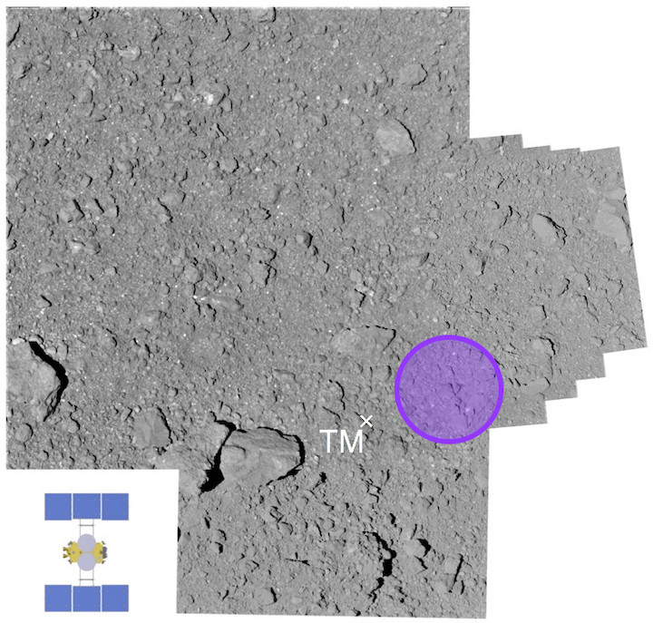
- Figure 1: Location where Hayabusa2 will touchdown.
The touchdown aims for inside the purple circle (about 6m diameter). The cross indicates the location of the target marker. The illustration of the spacecraft in the lower left is the same scale as the picture. (Image credit *:JAXA).
During touchdown, the spacecraft will descend towards the center of the circle shown in Figure 1, which is located 4 or 5m away from the target marker location. As the guidance error of the spacecraft is a maximum of 2.7m, the spacecraft can land in a circle of radius 3m. Although this size of this site is just barely sufficient, we will try to touchdown here.
Figure 2 shows an animation of the area in Figure 1 in three dimensions (3D) using a DEM (Digital Elevation Map). You can see the elevation of the area surrounding the touchdown location.
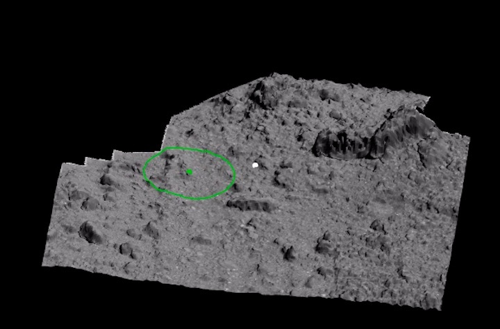
Figure 2: The appearance of the region surrounding the touchdown site.
The animation is created from a DEM (Digital Elevation Map). (Image credit: JAXA.)
Before our arrival at Ryugu, we planned to touchdown in a flat area about 100 m wide, but ultimately, we selected a region with a diameter of about 6m (radius 3m). We were able to improve the necessary landing accuracy using a technique called “pinpoint touchdown”. Pinpoint touchdown was originally planned for touching down around the artificial crater generated with the onboard small carry-on impactor (SCI), but the environment we discovered on the asteroid surface has made this method necessary from the start. More details on pinpoint touchdown can be found in our press briefing from February 6.
(A) Latitude is within a range of about ±30 degrees
Hayabusa2 mainly descends and rises along a straight line running between the Earth and Ryugu (Figure 3). This is because the Earth and the Sun are in the same direction as seen from Hayabusa2, during the period when Hayabusa2 is exploring Ryugu, and it is necessary to keep either the solar cells or spacecraft antenna turned towards the Sun or Earth. During touchdown, the spacecraft changes its attitude so that the paddles of the solar cells are parallel to the surface of Ryugu, but sunlight needs to continue to strike the cells. Therefore, in order to prevent the attitude of the spacecraft during descent and touchdown from changing greatly, the latitude of the touchdown is confined to a range of about ±30 degrees.
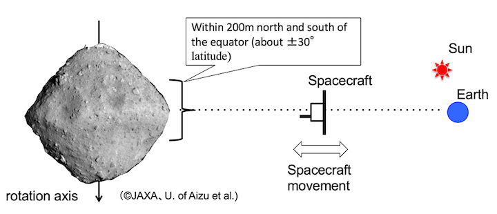
- Figure 3: Latitude range suitable for descent and touchdown on Ryugu. (Image credit *: JAXA)
(B) The inclination of the surface averages to within 30 degrees
As mentioned above, Hayabusa2 needs to touchdown with an attitude that keeps the solar panels parallel to the surface of Ryugu. If the touchdown site is partially inclined, the attitude of the spacecraft will also be inclined and as this inclination increases, the sunlight hitting the solar cells weakens. This restricts the inclination of the surface to be within 30 degrees.
(C) There should be a flat region about 100m in diameter(Note* 1)
The accuracy of the navigation guidance system when autonomously lowering the spacecraft is estimated to be approximately ±50m. For this reason, it is necessary to have a flat area about 100m in diameter in order to safely touchdown.
(D) Boulders should be 50cm is less in height(Note* 2)
The sampler horn that collects material from the surface has a length of about 100cm. Therefore, when the tip of the sampler horn is on the ground, it is desirable that the height of the boulders is 50cm or less so that the body of the spacecraft does not come into contact with the boulders.
(E) The surface temperature is less than 97℃(absolute temperature 370K)
Temperature at the touchdown site must be lower than this limit in order to prevent the equipment installed on the spacecraft failing due to becoming too hot due to the ground surface heat.
Based on the data obtains during the operations to date, we selected places that fulfilled the above prerequisites (A) to (E) and then narrowed down the location from these touchdown candidate sites.
- (Note*1) Prior to changing to the pinpoint touchdown technique, we assumed a guidance accuracy of about ±50m. The plan was therefore to touchdown in a flat region about 100m wide.
- (Note*2)These conditions were set as of August 2018. In the subsequent study, we slightly relaxed the conditions and specified a “maximum boulder size of less than 70cm in height”.
2. First narrowing-down of the candidate sites for touchdown
Narrowing-down the candidate sites was done in the following three phases:
Phase 1: Safety analysis
From the shape model of Ryugu, we comprehensively evaluated features such as the angle of the Sun at each location, the inclination of the surface and topological irregularities to give a “safety score” (Figure 4). Looking at this score, you can see that the region along the equatorial ridge of Ryugu is the best for safety.
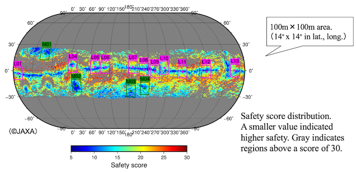
- Figure 4: Distribution of the safety score for touchdown derived from the shape model (Image credit: JAXA).
Based on this safety score, we selected 100m-wide candidate sites from 11 low-latitude areas and 4 mid-latitude areas as places with the greatest safety. “L...” denotes a low-latitude spot, while “M…” is a candidate site at the mid-latitudes.
Phase 2:Image evaluation
We next evaluated the candidate sites from the viewpoint of the number of boulders, the degree of flatness and whether there are obstacles on the eastern side, using images from the Optical Navigation Cameras (ONC) captured so far. (To descend onto a rotating Ryugu, the spacecraft will approach from the east as seen from the surface of the landing site. Therefore, if an obstacle such as a large boulder is on the east side of the candidate site, there is a danger of striking this with the spacecraft during the descent.)
As a result of this analysis, the number of candidate sites was narrowed down to four locations at low-latitudes (L05, L07, L08, L12) and three locations at mid-latitudes (M01, M03, M04) (Figure 5).
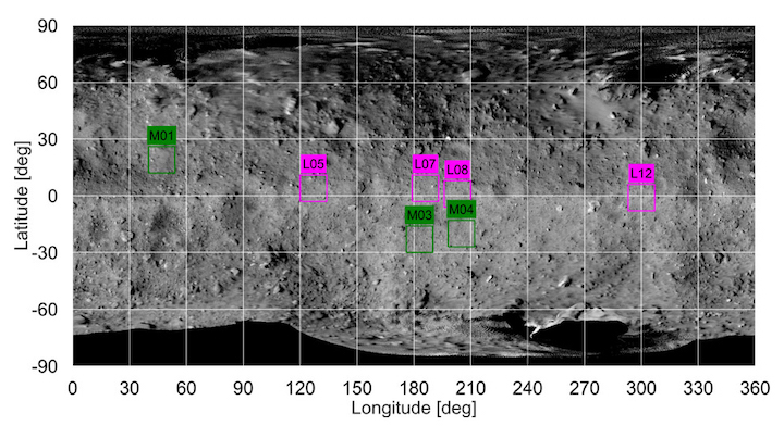
- Figure 5: Seven locations of touchdown candidates after selection via image evaluation. (Image credit *:JAXA)
Phase 3:Feasibility Analysis
From the seven candidate sites selected so far, we examined whether all the conditions for achieving touchdown could be satisfied.
Regarding the surface temperature, all seven locations fulfilled this condition. There were also no problems with any of the seven sites for uninterrupted communication with the ground station.
We also examined the number density of boulders at each point. Since the surface of Ryugu is quite rocky, this condition was the most important point in finally determining the touchdown candidate site.
From the images obtained so far, we created a map of boulders in the areas of each of the seven candidate sites (Figure 6).
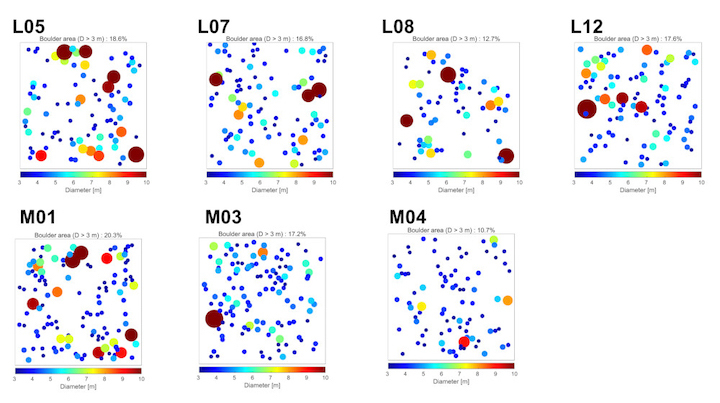
- Figure 6: Boulder map. Each map shows the distribution of boulders 3 m or more in diameter based on the images of Ryugu. Size is indicated by color, with brown showing boulders 10 m or more in size. (Image credit: JAXA)
Using these boulder maps, we identified places where the boulders covered as low a percentage of the areas as possible, finally choosing the point “L08” as the touchdown candidate site and selecting two further places, “L07” and “M04” as backup choices (Figure 7).
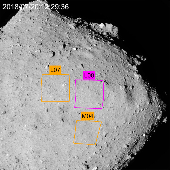
- Figure 7: Touchdown candidate site “L08” was finally chosen, with candidate backup sites “L07” and “M04”. (Image credit *: JAXA)
In parallel to this selection process, we were using the data obtained from the scientific observations to also ask “Are we able to collect samples at this location to address the mission’s scientific goals?”, “Is there a difference in the safety level depending on the number of boulders?” and "Is the expected yield of the sample sufficiently high?”.
This analysis revealed that the material on the surface of Ryugu has roughly the same diversity at all locations, and the yield of the sample estimated from particle size on the surface did not vary by very much. Therefore, from the viewpoint of the scientific evaluation, it was concluded that “L08” should remain the main candidate site with the backup sites as “L07” and “M04”.
This was the discussion in August 2018. Although the details are not added here, a similar discussion was also held for the landing sites for MINERVA-II1 and MASCOT, whose touchdown locations were finally chosen as shown in Figure 8.
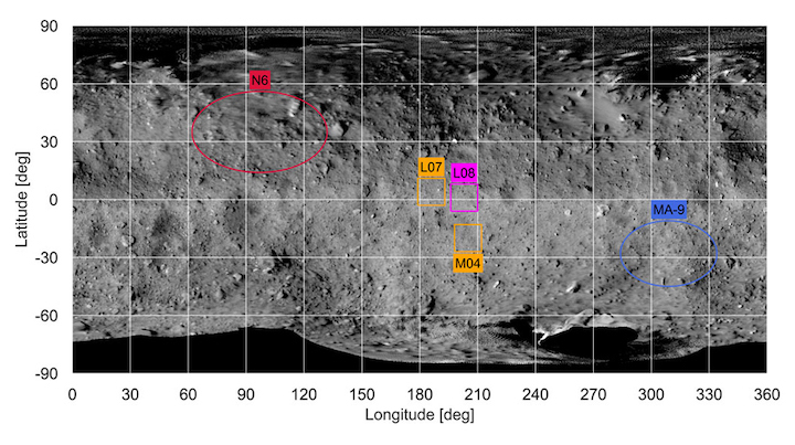
- Figure 8: Touchdown candidate sites (L08, L07, M04), the MINERVA-II1 landing candidate site (N6) and MASCOT landing candidate site (MA-9). (Image credit *:JAXA.)
3. Further narrowing down of the candidates for touchdown
From September 2018, we did a series of operations to bring Hayabusa2 close to the surface of Ryugu for rehearsal touchdown operations and the deployment of MINERVA-II1 and MASCOT. During these times of close approach, we further investigated the touchdown candidate site, L08. The results revealed that the touchdown would still face considerable difficulties due to the distribution of boulders within the L08 area. However, within L08, there are some areas where there are fewer boulders and the place where the conditions are likely to be best for touchdown was denoted L08-B. Figure 9 shows L08-B and the region around L08-B is shown in Figure 10.
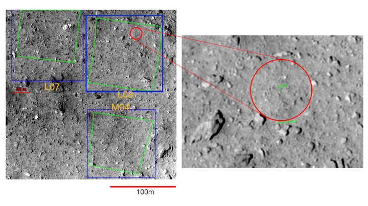
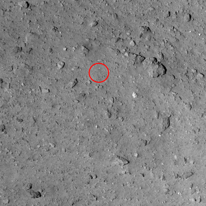
Figure 9: The red circle is L08-B within the touchdown candidate site, L08. The diameter of the red circle is about 20m. (Image credit *:JAXA)
- Figure 10: The area surrounding L08-B. The red circle is L08-B. This image was taken with the Optical Navigation Camera – Telescopic (ONC-T) from an altitude of about 1.9 km on October 3, 2018. (Image credit: ※:JAXA)
As a rehearsal for touchdown on October 25, 2018, the target marker was dropped towards L08-B. The resultant landing point for the target marker was about 5 m from L08-B. After further examination of the vicinity of the target marker, two places for possible touchdown were considered: L08-B1 and L08-E1 (Figure 11).
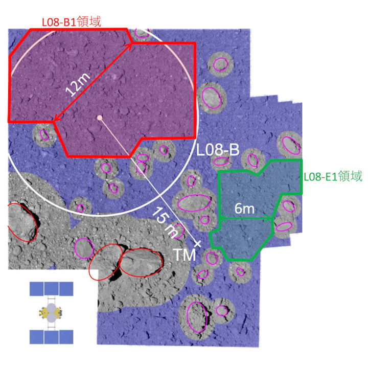
- Figure 11: Touchdown candidate sites L08-B1 (red) and L08-E1 (green). The white circle indicates the area of L08-B, while the cross is the location of the landed target marker. (Image credit *:JAXA)
During this descent, we also confirmed the accuracy of the guidance navigation system on Hayabusa2 is about ±15m. This is a much greater accuracy than our initial estimate of about ±50m. However, for an accuracy of ±15m, a flat area of 30m or more in width is still required and no such area is visible. We therefore decided to adopt an alternative touchdown method using this previously dropped target marker. This is the “pinpoint touchdown” method, which allows us to guide the probe more accurately.
From Figure 11, we estimated the size and height of the large boulders and examined the possible safe places for the spacecraft to touchdown. If the sampler horn touches the surface in the area shaded blue in Figure 11, the spacecraft will be safe. From this analysis, L08-B1 and L08-E1 were narrowed down as acceptable landing sites near the target marker.
While L08-B1 is a little further from the target marker, it has the broader width at 12m. Whereas, L08-E1 is closer to the target marker but narrower, with a 6m width. By considering the accuracy of the navigation guidance of the spacecraft, it was ultimately decided that L08-E1 would be the touchdown site, as first shown in Figure 1. As mentioned at the beginning of this article, the final navigation guidance accuracy is ±2.7m with the pinpoint touchdown method. Utilizing this accuracy, we can aim for a circle of diameter 6m at L08-E1 (Figure 1).
This is the conclusion to the long tale of how we selected the touchdown candidate site.
* For the images of Ryugu that are the background to these figures, the image credit is JAXA, University of Tokyo, Kochi University, Rikkyo University, Nagoya University, Chiba Institute of Technology, Meiji University, University of Aizu and AIST.
Hayabusa2 project
2018.02.19 (Translated 2019.02.21)
Quelle: JAXA