After a week and a half long river trip on Pegasus, the second of four Core Stage structural test articles (STA) arrived at the Marshall Space Flight Center in Huntsville, Alabama, to start final preparations for a series of structural tests planned to begin this Summer.
The Space Launch System (SLS) Program completed construction of the STA at NASA’s Michoud Assembly Facility (MAF) in New Orleans.
Following assembly of the three-piece intertank STA, Core Stage prime contractor Boeing and facility operations and maintenance contractor Syncom Space Services (S3) placed the hardware on the new Multipurpose Transportation System (MPTS), which rolled the STA down to the Pegasus barge in its first official SLS duty on February 22.
Eventually, the MPTS will move finished Core Stages to and from Pegasus for trips between NASA assembly, test, and launch facilities in the region.
IT STA assembly completed at MAF
The intertank structural test article is the second of four completed, following the engine section STA that was shipped to Marshall last Spring and recently completed testing. It will be followed to Marshall by a liquid hydrogen (LH2) tank STA and a liquid oxygen (LOX) tank STA later this year.
The intertank is the only one of the Core Stage’s five major structural elements that is not welded. The other four structures are the forward skirt, the LOX tank, the LH2 tank, and the engine section. The barrel-shaped intertank is positioned between the LOX and LH2 tank on the stage, with a large crossbeam that runs through the middle where the forward end of the two SLS solid rocket boosters (SRB) attach.

Core Stage elements. Credit: NASA
The panels that make up an intertank barrel are bolted together because they are too thick to be welded. There are eight panels around its circumference, with two thrust panels at either end of the crossbeam. The outside of the panels is reinforced in places with longitudinal and circumferential ribs.
“That was a very challenging manufacturing process because it’s ribbed on the outside [but] not the inside,” SLS Stages Dry Structures Manager Heather Haney explained. “It took a long time to get those panels made.” The barrel was bolted together with the large crossbeam in a structural assembly jig at MAF over the last half of 2017. The crossbeam was loaded into the jig first and the eight panels were built up around it.

Intertank flight article removed from structural assembly jig, June 2017. One of the thrust panels can be seen on the left, along with the reinforcing ribs running up, down, and around the outside. Credit: NASA/Michoud/Steven Seipel
The STA consists of the main intertank qualification article, which is essentially a carbon copy of just the flight intertank’s structural elements, and simulators representing the part of the LOX and LH2 tanks that attach at the top and bottom of the intertank, respectively. The ends of the three hardware pieces have built-in rings that form an attachment flange at the interfaces between them. As will be the case for the real thing, three-hundred and sixty bolts, one for each degree around the circumference, mate each flange.
The areas around the flange are also outfitted with hardware to chill them down to cryogenic temperatures to better represent the launch environment the rocket will experience. “You can see in two places they’ve got the ‘Versa-Foam,'” SLS Stages Integration Manager Tim Flores noted.

Intertank STA showing light yellow rings of ‘Versa-Foam’ insulation covering the inside and outside of the mated flanges. Liquid nitrogen will run through the silver tubes to chill down the area. Credit: Philip Sloss for NSF/L2
“It’s not the type of stuff that we would do for the flight article, it’s just to create insulation so we can pump liquid nitrogen through there. The intertank is between the LOX tank and the hydrogen tank, so we’ve got to cool both of those two interfaces.”
The pieces were stacked vertically in Building 110 at MAF, the Vertical Assembly Building (VAB) that adjoins the main Building 103 on its west end. “We ended up having to use two cells which is pretty unique,” Flores said. Cell A in the VAB at MAF has been used for stacking launch vehicles since the Saturn days and Cell D was recently renovated into a second stacking or integration cell for SLS.

Stacking rockets in Cell A at MAF over the years. Saturn V S-IC first stage left, Shuttle External Tank right. Credit: NASA
Flores explained why both cells were used: “It was access. First access to the two cells, and then access to where you needed to get to, to be able to do the Versa-Foam, because Cell D has a moving platform that actually can go up and down it, but it only goes so far. So using that one and the unique stacking sequence lended itself to being able to get to where we needed to do the Versa-Foam.”
In addition to the two stacking cells, Building 110 is also the home to the Vertical Assembly Center welding tool, a washing machine in Cell E that cleans the inside of the LOX and LH2 tanks, and next door in Cell F, a hydrostatic proof test facility for verifying the integrity of LOX tank welds. With SLS getting ready for its first flight, there are nearly two full sets of hardware currently being processed to ship out of MAF.

LH2 qual tank lifted into Building 110 Cell E washing machine, June 2017. Cell F to the left, Cell D right, blue VAC structure foreground. Credit: NASA/MSFC Michoud/Jude Guidry
The intertank STA was surrounded by propellant tanks during stacking, creating some of the access realities that Flores noted. The inside of the flight LH2 tank was being washed in Cell E and the LOX tank STA was being proof tested in Cell F at the same time.
First SLS use of new ground transporters
After the STA was fully assembled, cranes lifted it out of the vertical integration cell, rotated it to horizontal, and placed it over the new Multipurpose Transportation System or MPTS parked in the transfer aisle of Building 110. The MPTS is support equipment that allows for careful ground transportation of the large Core Stage hardware. Structural support hardware attaches from the vehicle hardware to automated mobile transporters called self-propelled mobilized transporters (SPMT).

Workers attach STA to ground transporter in the transfer aisle of Building 110 at MAF, February 2018. Credit: NASA/Michoud
The simulators on both ends of the intertank STA are attached to hardware interface structures (HIS). In the case of the STAs, a common HIS is used on both ends; when the full Core Stage or mockup Pathfinder are moved, a forward HIS will be attached to each SRB attach fitting in the front, and one common HIS will be bolted to the engine section area in the back. Each HIS is attached to a table-shaped multipurpose carrier (MPC). The MPCs also have pedestals attached to them that are used to secure the vehicle and MPTS when stationary, such as to the Pegasus barge.

Artist conception of intertank STA on MPTS. Credit: NASA
As commanded by operators, four remotely-controlled SPMTs roll underneath the MPCs (two for each) and pick them up to move the whole assembly. “The SPMTs themselves are actually pretty amazing because they can crab, they can go any direction, they can turn on a dime,” Flores said. “Then they put them in group mode, whether it be two, whether it be four, but they all move together wirelessly. As close as they are right now, we just wired them.”
Once the STA was fully secured to the MPTS, its first move was backwards. “As soon as the IT structural test article was ready to go we moved it back east to get it out of the way,” Pat Whipps, the SLS Stages Resident Manager at MAF noted. The washing machine cycles on the flight LH2 tank were done and it needed to proceed directly to its next station. In fact, the LOX tank STA proof test was also complete but it would have to wait for the STA to leave and its next station was still occupied by the flight LOX tank.
On February 22, the SPMTs rolled the STA assembly over an approximately mile-long route from Building 110 to where the Pegasus barge was waiting at the dock. Although they have different speed settings, Flores said SPMT operators will tend to move at the slowest of their speed settings when carrying space hardware. The launch and ascent loads that the hardware is designed to take are not along load paths it will see on the MPTS, where it is being transported horizontally.

SPMTs move the intertank STA down Saturn Blvd at MAF, 22 February 2018. The pedestals that attach the whole MPTS to the barge can be seen “hanging” over the sides of the SPMTs. Credit: Philip Sloss for NSF/L2
After rolling the STA onto the barge, the SPMTs positioned the pedestals over mounts on the deck inside and lowered them down. Once the pedestals were secured to the barge deck, the SPMTs were repositioned in the barge for the trip. “On the way there, we’ll have them riding at the same time, but they’ll be disconnected,” Flores said before the trip.
“They’ll be moved up to the front of the barge, locked and chained down. The same thing we’ll do with all those D-rings that you see around on the MPCs. Everything will be locked down on the barge, but they’ll be separated.” Flores also noted that the SPMTs are needed back at MAF before the barge can return, so they will be returned by ground transportation once they have finished their work at Marshall.

View inside Pegasus showing square pedestal mounts and rows of D-rings on the barge deck, April 2017. Credit: Philip Sloss for NSF/L2
Pegasus took a different river route from MAF to Marshall this time. When the engine section STA was delivered last Spring, the barge was towed by tug boats up the Mississippi River to the Ohio River and then to the Tennessee River. For this trip, the barge route went up the Tombigbee River to the Tennessee via the Tombigbee-Tennessee Waterway.
“We’ve prepared the Pegasus to be able to handle the Tombigbee,” Flores said before the trip. “We had some antennas and some things that were about four feet higher than they needed to be. It’s all about clearing the bridges. That helps us and then we understand how we can ballast a little bit further and get a little bit deeper and so we think there shouldn’t be an issue on the Tombigbee. That was always the problem was there’s more bridges and they’re all shorter.”

Infographic on the Pegasus barge, showing route through Tombigbee and Tennessee Rivers. Credit: NASA
Intertank test stand
Once Pegasus arrived at the dock at Marshall, the SPMTs again picked up the STA assembly and made the drive to the intertank test stand in Building 4619. This is a much longer drive than at MAF. “They’re estimating that whatever it is — the six or seven miles that it is — is going to take us thirteen hours, so it’s going to be a long day,” Flores said prior to the trip. The roll was completed on March 6.
“We’ve been working on our test stand many months prior to this, so we had to do a lot of work to get the stand ready to accept that test article,” Haney said, picking up the story. “So once this gets to Marshall, it will be outside and we will break it over and then we have to do a lot of work.”
“We have a lower load ring that will attach to it and then we will have an upper load ring. When those are attached we’ll back it into the 4619 test stand and then we will continue with the build up.”

Intertank test stand in Building 4619 under construction in 2017. Credit: NASA/MSFC
The STA is placed in the stand upside down, with the crosshead that moves to help apply loads pushing down on it during tests. “We’re saying roughly four weeks to finish up to get it ready to put into the test stand and then we won’t start testing probably until around August,” she noted. “So there’s a lot of build up that has to continue after that gets in.”
The test article is also covered with instrumentation and wire harnesses which have to be connected to a data acquisition system to record measurements during all the test runs. The structure itself will be surrounded by the test stand elements and hooked up to hydraulic actuators that will apply the different forces to the STA. The cryogenic piping in the STA will also be connected to liquid nitrogen supplies for chilling down areas in some test cases.

Artist concept of the intertank STA in the test stand. Credit: NASA/MSFC
Haney explained how the test stand will structurally attach to the STA: “There’s six panels on each side and so then what we have is what we call a belt buckle — it’s an orange piece with a hole in it. There’s over a hundred hydraulic actuators for this whole test. About 24 of those, 12 on each side, they attach to that belt buckle.”
Referring to the covers over the SRB attach fittings, she continued: “That was what we call a ‘top hat.’ Those will sit in the belt buckle where we have all these hydraulic actuators that will apply the forces that we’ll see during launch and ascent.”
“So all the forces that it is going to see are going to get pushed into the 27-foot thick concrete floor,” she explained. “There’s lower load rings that are attached to the concrete and there’s an upper load ring that is attached to the crosshead — that’s what will push those forces on it.”
Dozens of tests
Once the STA is fully installed and the test stand is configured, a series of dozens of test cases will be run. “Right now it’s about forty-eight test cases,” Haney said. “As we get closer to test and we refine things, then we may do less. But whatever we do as a team we make sure that we have enveloped all the loads that we need to see, [so] that we can say that it’s qualified for flight.”
Preparing to run the cold test cases will generally take a long time. “If you’re going to run a cryo case, you have to get it cold enough,” she explained.

‘Top-Hat’ covering one of the two SRB attach fittings on the intertank STA. Credit: Philip Sloss for NSF/L2
“So it could up to six hours just to get it cold enough and then you go run the actual test case. Depending on the case, it depends on how much load you’re adding and we add load in increments of 20 percent and up until we get to 100 or if we’re doing ultimate it would be up to 140 and then we back down the same way. And every time we increment 20 percent we flag a data scan, we look at it, we say we’re good to go, and we continue up.”
Limit load cases test the structure to 100 percent of the maximum loads (or combination of loads) expected to be seen in flight, while ultimate load cases test the structure to 140 percent of those maximum expected loads.
Similar types of forces will be put on the intertank article as were applied to the engine section. “It’ll be the same, but it may be different ways we do it,” she said. “It’s going to see a little higher forces than we saw on the engine section, remember the solid rocket boosters attach here and so it’s got to be beefy where it attaches to our intertank.”
As the Dry Structures Manager, Haney will be watching each test closely from the test control room. “I was there for every test we did on the engine section and I’ll be there for every test we do on the intertank,” she said.

Crew at MAF stands in front of IT STA loaded on Pegasus for trip to Marshall. Credit: NASA/Michoud/Steven Seipel
When asked how long the test series will run, she said: “Probably until around the first of January. We don’t test every day, you know you run a certain number of test cases and then Boeing, our partners, they go off and they look at that data and make sure we got what we need.”
“Because it’s NASA and Boeing, hand in hand,” she emphasized. “When we add load, Boeing is going ‘yeah, that’s good, continue.’ So we’re all looking at it and making sure that it’s ready [to proceed]. We don’t run [tests] every day, but it’ll take about three to four months to do those.”
Engine section structural tests finish with ‘margin test’
The engine section STA tests were recently completed at Marshall in a load test area of Building 4619 near where the intertank STA will be tested.

NASA Advisory Council presentation slide on engine section structural testing.
One of the decisions that was pending for a long time was whether or not to do a “test to failure” after each STA completed its required series of tests. For the intertank STA, Haney said, “We haven’t decided that for sure yet, but more than likely we will.”
The engine section STA was the first to complete its full test series and after those were done, the decision was made to do a “margin test.” The structure was taken up to a factor of safety of 2.0 or 200 percent of the maximum expected loads. “We didn’t go to failure, but we did [take it] to 200 percent,” Haney said.
The 200 percent loads were held for five minutes. “I’ll say we were all holding our breath — ‘OK, we’re here, alright counting down,'” she added. “It went really well. It’s almost like, you got all worked up prior to the 200 percent mark and you’re like ‘that’s it?’ The engine section tests went very, very well.”
When asked if the structure ‘failed’ at 200 percent, she explained: “It was yielded in areas, so it did. But it wasn’t like you heard a loud crack. It was very good.”
Haney said the data from the margin test was very close to what was predicted by structural models. “Our Boeing guys did a really good job with their predictions. And our NASA guys, you know we’re all hand in hand doing this. But Boeing did a really good job with their predictions. And so that’s going to tell us a lot about future needs.”
Quelle: NS
---
Update: 25.04.2018
.
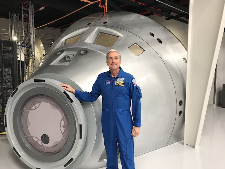
Exciting to see the new Orion simulators at the Astronaut Training Experience (ATX) @ExploreSpaceKSC . They even let one of the old astronauts sit in the commander seat! Anyone for Mars??
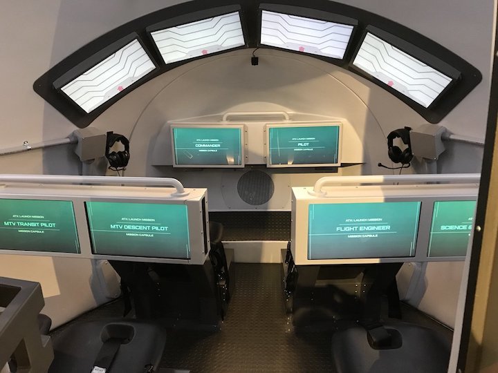
Exciting to see the new Orion simulators at the Astronaut Training Experience (ATX)
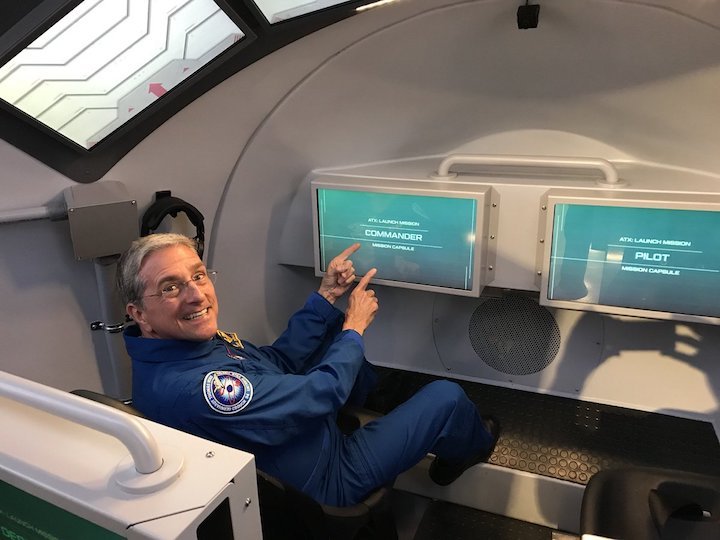
Quelle:
Veteran of four space shuttle missions, STS-65, 70, 83 and 94, author of Orbit of Discovery, scientist, educator, and professional speaker.
---
Update: 10.05.2018
,
NASA’s Orion spacecraft getting closer to finally flying again
"Our destiny is to explore, so you want to get your tests behind you."
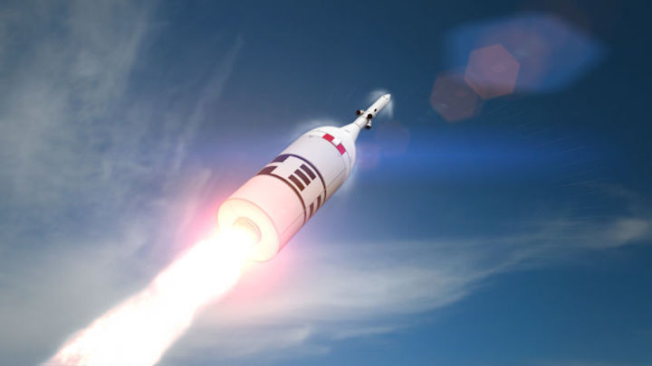
It's been a long three-and-a-half years since the Orion spacecraft first launched into space in December 2014, making a successful shake-out flight. But now, NASA’s program aimed at building a large, deep-space capsule capable of sending astronauts to and from lunar orbit is finally ramping back up toward a series of test flights.
In less than a year, a boilerplate model of the Orion spacecraft will be jettisoned from its rocket at 55 seconds after liftoff to test the vehicle’s launch abort system. Provided that goes well, about a year after that, the Orion spacecraft will be sent into lunar orbit for longer than a week for a shakedown cruise. Finally, as early as June 2022, two to four astronauts will fly aboard Orion into lunar orbit, sending humans into deep space for the first time since 1972.
This isn’t exactly a rapid cadence of flights, but three missions in four years would represent a remarkable increase from the vehicle’s flight rate to date—one in 13 years. “Our destiny is to explore, so you want to get your tests behind you and get humans on the spacecraft, and start that exploration,” Annette Hasbrook, an assistant manager for the Orion program in Houston, told Ars.
Abort test
A few weeks ago, Johnson Space Center invited reporters to view the Orion spacecraft that will undertake the Ascent Abort-2 test flight next April. The craft was constructed at NASA’s Langley Research Center, and technicians in Houston are outfitting the crew module with 200 sensors. Although no Starman or Mannequin Skywalker will sit inside—there won’t even be seats—the vehicle will have sensors in the vicinity of where astronauts will be seated to determine forces that astronauts would experience during the test.
NASA intends to conduct the abort test in April 2019 at Kennedy Space Center in Florida. A stubby first-stage booster from a Peacekeeper missile, modified by Orbital Sciences Corporation, will lift the Orion crew module and launch abort system to just under 10km, reaching Mach 1.3. At that point, under maximum dynamic pressure, the launch-abort system’s motor will fire, pulling the crew vehicle 3km upward and away from the rocket in just 15 seconds.
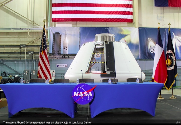
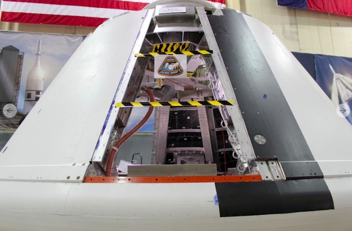
With this one test, NASA will attempt to gather data for a variety of abort scenarios, so engineers have chosen a target suite of conditions such as angle of attack and velocity that most defines the situations they’re concerned with. “We couldn’t do a worst-on-worst case for one area because it wouldn’t tell us about another area,” said Jon Olansen, manager of the Ascent Abort Crew Module for NASA. “So we wanted to try and find a difficult region that can inform all of the regions.”
The agency will collect data from the test to affirm its simulations for a range of conditions in which something goes wrong with the Space Launch System rocket, and the launch-abort system needs to pull the spacecraft quickly away. If everything works as intended, NASA will be ready to produce a final version of the launch-abort system for the first crewed flight.
America’s spacecraft
This flight, known as Exploration Mission-2, may occur sooner than agency planners had thought. Until now, the biggest hurdle between the first deep space test flight of the Orion vehicle (likely in 2020) and the first crew flight has been the need to refurbish a large “mobile launcher” tower. This structure supports the testing and servicing of the massive SLS rocket, moves it to the launchpad, and provides a platform from which it will launch.
Between the first test flight and second flight of the rocket, NASA had intended to upgrade the SLS rocket’s upper stage to give it more kick in sending larger payloads deeper into the Solar System. This larger and longer upper stage, known as the “Exploration Upper Stage,” will necessitate significant changes to the mobile launcher. The agency estimated it would take 33 months to accomplish this work, creating a nearly three-year delay between the first and second flights of SLS, and accordingly between the uncrewed and crewed deep space test flights of Orion.
Now, however, NASA has said it will build a second mobile launcher for the more powerful version of the SLS rocket. In turn, the agency has decided to fly the first crewed mission of Orion on the original configuration of the SLS rocket, meaning there is no longer the 33-month “bar” between the two flights.
“Being able to pull that bar out and to have the opportunity to get humans into space a little bit earlier is fantastic,” Hasbrook said.
This has allowed the Orion program to push the crewed launch of its vehicle forward to June, 2022, about a year earlier than previously anticipated. Officials at NASA headquarters have yet to set a formal launch date for Exploration Mission-2 now that the mobile launcher issue has been solved. A decision is likely to come this summer.
Really, it cannot come soon enough. The agency has been “developing” the Orion spacecraft in one form or another since 2005, and it presently spends about $1.35 billion a year on the program, regardless of when it will fly. If Orion is “America’s spacecraft” as the agency says, it's time for America to see it in action.
Quelle: arsTechnica

