.
4.10.2015
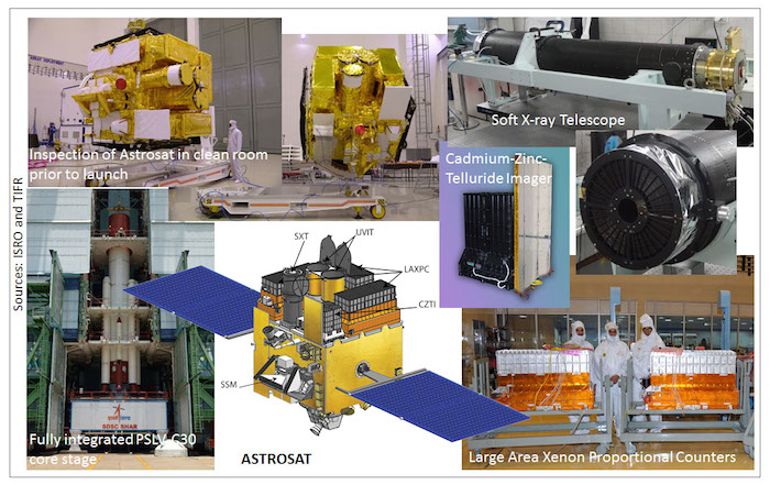
The first Indian astronomy satellite Astrosat was launched on 28th September, 2015, by the Indian Space Research Organisation (ISRO) from Sriharikota, on a PSLV (Polar Satellite Launch Vehicle) rocket. Astrosat has unprecedented capability to simultaneously observe cosmic objects in visible light, the ultraviolet waveband and the entire X-ray waveband from very low energy to very high energy X-rays. This unique ability to observe the universe in multi-wavelengths, simultaneously, is aimed at performing cutting-edge research in astrophysics.
Researchers from the Tata Institute of Fundamental Research (TIFR) have led this multi institutional effort and have made significant contributions to the design, fabrication and development of three out of five payloads that are on board Astrosat.
The Large Area Xenon Proportional Counters (LAXPC), a Soft X-ray Telescope (SXT), and a Cadmium-Zinc- Telluride Imager (CZTI), all of which will observe the universe in the X-ray wavebands, are the three payloads built in the Department of Astronomy and Astrophysics (DAA) of TIFR Colaba, Mumbai. These instruments demonstrate a major Indian technological advance. In addition, DAA/TIFR has significantly contributed to the twin Ultraviolet Imaging Telescopes (UVIT) on board Astrosat. ‘The instruments developed by TIFR will give us a capability unrivalled in the world for the next 5 to 10 years. We look forward to some great science results’ says Prof. S. Trivedi, Director TIFR.
Cosmic objects (stars, galaxies, quasars etc.) emit in multiple wavebands. Therefore, in order to unravel their mysteries it is essential to observe them in as many wavebands as possible. As X-rays and ultraviolet (UV) energy from cosmic objects cannot penetrate the Earth's atmosphere, suitable instruments must be sent above the atmosphere by satellites. TIFR has been a pioneer in X-ray astronomy research in India. Soon after the discovery of the first extra-solar X-ray source in 1962, TIFR scientists built X-ray instruments for astronomical research, and sent them above the atmosphere by sub-orbital rockets and balloons. Astrosat is a legacy of these activities. As Prof. P.C. Agrawal, one of the lead scientists who gave shape to the concept of this mission, says, ‘Astrosat is a quantum leap from previous modest sized payloads on other Indian satellites. It is an internationally competitive observatory that will enable Indian scientists to work in frontier areas of high energy physics.’
The LAXPC detectors with the largest collecting area among any X-ray instrument ever built in the world, have been fully fabricated at TIFR, by a series of leaders, namely Prof. P.C. Agrawal, Prof. R.K. Manchanda, Prof. J.S. Yadav, and Prof. H.M. Antia. For the next 5 to 10 years LAXPC will be the only instrument in the world that will be able to study X-ray intensity fluctuations of cosmic objects on time scales as small as a milli-second. This will be essential to probe the fundamental physics of exotic objects, like black holes and super-dense neutron stars.
The SXT is the first X-ray focusing telescope built in India. The SXT will conduct imaging and X-ray spectroscopy of hot plasma in cosmic sources and the absorption of x-rays by intervening matter. The SXT team at TIFR, overcame major challenges in building and assembling the mirrors of this X-ray telescope. ‘It is common knowledge that X-rays easily penetrate through materials but it is extremely difficult to focus x-rays with a telescope. Placing the 320 mirrors in the telescope, required great precision’, says Prof. K.P. Singh, lead scientist of the SXT team. The focal plane camera for the SXT containing a cooled charge coupled device (CCD) was built in collaboration with the University of Leicester (UK).
The CZTI, will image celestial objects in the high-energy X-ray band using a coded mask. It has the ability to also perform unique polarization measurements in very high energy X-rays. Built under the leadership of Prof. A.R. Rao of TIFR, the team overcame several challenges to ensure a uniform response from a large number of detectors, as the development of such detectors and electronics for use in high-energy X-ray imaging is a recent technology. Scientific data obtained through Astrosat will be distributed from a few payload operation centres (POC), two of which will be located at TIFR. These two POCs, will control the operations of SXT and LAXPC, making DAA/TIFR a major centre of worldwide X-ray astronomical activities for the next few years.
Astrosat will be available to the Indian astronomy community as an observational opportunity. It will address fundamental scientific problems that cannot be probed in terrestrial laboratories. These will include testing Einstein's general theory of relativity, studying superdense cold matter deep inside a neutron star which is a fundamental problem of particle physics, and understanding flow of matter in astronomical scales, often in extremely strong gravity regions, relativistically accelerated plasma jets, extremely hot ionised plasmas, and absorption by cold matter. Astrosat will observe a variety of objects in the universe, such as black holes, neutron stars, white dwarfs, explosive events like supernovae, stars, galaxies, and clusters of galaxies.
Quelle: Tata Institute of Fundamental Research, Mumbai.
-
ASTROSAT mission
ASTROSAT – India’s first dedicated astronomy satellite
To understand the nature of cosmic sources, their radiation processes and environment, it is necessary to measure their emission over the entire electromagnetic spectrum. Since intensity of most cosmic sources varies with time, the variability being wavelength- dependent, it is necessary to make simultaneous observations in different wavebands. Most of the current space astronomy observatories are dedicated to a particular waveband e.g. X-ray, UV etc and therefore, usually multiwavelength studies have to be made from coordinated observations with different satellites. There are logistical problems in making simultaneous and coordinated studies of a specific object from different satellites and ground-based telescopes. As a result, despite a large number of such multiwavelength observation campaigns, very few sources have so far been studied over wide spectral band leading to poor understanding of the underlying physical processes. The most efficient and effective approach is to have a dedicated satellite such as ASTROSAT with several co-aligned instruments covering the desired spectral bands so that simultaneous observations in all the desired wavebands is possible.
-
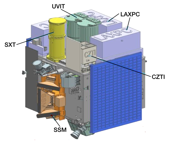
ASTROSAT is a multi-wavelength astronomy mission on an IRS-class satellite in a 650-km, near-equatorial orbit. It was launched by the Indian launch vehicle PSLV from Satish Dhawan Space Centre, Sriharikota on September 28, 2015. The expected operating life time of the satellite will be more than five years.
On board ASTROSAT are five astronomy payloads for simultaneous multi-band observations:
Twin 38-cm Ultraviolet Imaging Telescopes (UVIT) covering Far-UV to optical bands.
Three units of Large Area Xenon Proportional Counters (LAXPC) covering medium energy X-rays from 3 to 80 keV with an effective area of 8000 sq.cm. at 10 keV.
A Soft X-ray Telescope (SXT) with conical foil mirrors and X-ray CCD detector, covering the energy range 0.3-8 keV. The effective area will be about 120 sq.cm. at 1 keV.
A Cadmium-Zinc-Telluride coded-mask imager (CZTI), covering hard X-rays from 10 to 150 keV, with about 6 deg field of view and 480 sq.cm. effective area.
A Scanning Sky Monitor (SSM) consisting of three one-dimensional position-sensitive proportional counters with coded masks. The assembly is placed on a rotating platform to scan the available sky once every six hours in order to locate transient X-ray sources.
ASTROSAT will operate as a proposal-driven general purpose observatory, with main scientific focus on:
Simultaneous multi-wavelength monitoring of intensity variations in a broad range of cosmic sources.
Monitoring the X-ray sky for new transients.
Sky surveys in the hard X-ray and UV bands.
Broadband spectroscopic studies of X-ray binaries, AGN, SNRs, clusters of galaxies and stellar coronae.
Studies of periodic and non-periodic variability of X-ray sources.
Open observing time on ASTROSAT will start one year after launch, for which proposals will be invited from the astronomy community. The primary data archive for ASTROSAT will be located at the Indian Space Science Data Centre (ISSDC) near Bangalore, India.
The Ground Command and Control Centre for ASTROSAT is located at ISTRAC, Bangalore, India. Commanding and data download will be possible during every visible pass over Bangalore. Ten out of 14 orbits per day are visible to the ground station for long enough to accomplish full data download.
-
Ultra-Violet Imaging Telescope
Imaging in the ultra-violet regime with a spatial resolution of 1.8” ( ~ X 3 better than Galex) in a field of ~ 28’ provides many opportunities for Galactic and extra-galactic studies. Some of the objectives are listed below:
a) Time variations in UV of X-ray sources in coordination with the X-ray payloads
b) Star formation in nearby galaxies
c) Star formation in interacting galaxies
d) Star formation history of universe
e) Hot stars in Globular clusters
f) Planetary nebulae
Instrument Overview
UVIT is primarily an imaging instrument. Images are made simultaneously in three channels: FUV (130-180 nm), NUV (200-300 nm), and VIS (320-550 nm), in a field ~ 28’ circle. The spatial resolution (FWHM) is < 1.8” for the FUV and NUV channels, and it is ~ 2.2” for the VIS channel. In each channel, a set of filters are available, in the filter-wheels, for selecting a band. In the two ultraviolet channels, gratings are provided for low resolution (~ 100) slitless spectroscopy. The focussing optics is configured as twin R-C telescopes, each with a primary mirror with with effective diameter of ~ 375 mm.
The overall structure is shown in Fig. 2.1 Those parts of the telescopes which define locations of the optical elements are mostly made of Invar36, and the other parts are made of Aluminium alloy. The two telescopes are mounted on a cone-like structure of Titanium, which is attached to central cylinder of the spacecraft.
A cylindrical baffle extends over each of the telescopes for attenuating the radiation from off-axis sources. With these baffles the light reaching the detector from sources at 45 deg. from the axis is attenuated by a factor 109; with such attenuation the light reaching the detector from full Moon at 45 deg from the axis is less than the average sky background. In addition to these baffles, the doors act as sun shades as long as Sun is at > 45 deg from the axis and the plane containing the optical axis and normal to the doors.
In order to avoid contamination of the optics due to ultraviolet assisted reactions, bright-earth is kept away from the axis by >12 deg., and the sun is kept behind the sun-shield at all times even if UVIT is not observing.
The geo-coronal lines are very strong in day time, and a significant amount of solar radiation could be scattered by the other instruments on the spacecraft into the baffles. Therefore, the nominal observation period is restricted to the night time (In special cases, observations in day time could be considered).

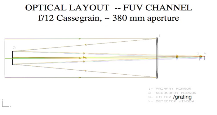
Fig. 2.2 Optical layout of the FUV telescope is shown. The primary mirror has a working diameter of 375 mm. The detector has a diameter of ~ 40 mm. The filters, each of diameter 50 mm, and the grating are mounted in a wheel at a distance of ~40 mm from the detector.
The plate scale is ~ 43“/mm. With a surface figure better than 1/50 waves rms (at 632 nm) for each of the mirrors, the PSF includes > 60% energy in diameter 1” at all wavelengths. In the NUV/VIS telescope, a beam splitter is used to reflect NUV and transmit VIS. Transmission leads to aberration in the VIS beam, and a cylindrical lens in used to reduce the aberration below 2” FWHM
.
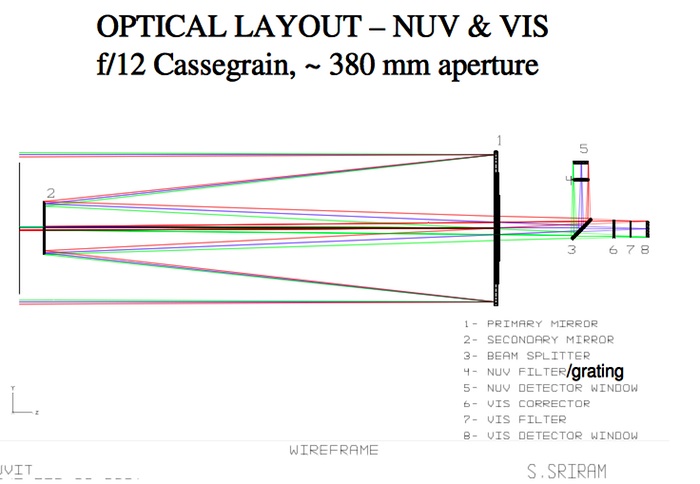
Fig. 2.3 Optical layout of the NUV /VIS telescope is shown. The primary mirror has a working diameter of 375 mm. A dichroic beam splitter is used for spectral division of the beam in NUV (reflection) and VIS (transmission). The detector has a diameter of ~ 40 mm. The filters, each of diameter 50 mm, and the grating (only for the NUV channel) are mounted in a wheel at a distance of ~ 40 mm from the detector.
Filters
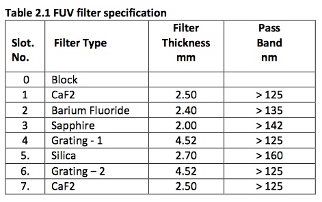
Filters for the three channels are listed in Tables 2.1 to 2.3. The transmission curves for the filters and the beam splitter are shown in Fig. 2.4 to 2.15. Thickness of each filter/grating is chosen such that the best focus is obtained at the same location for all the filters/grating of a channel. In OBS_ID, filters are identified as "F0, F1, ..." . Filters "F0, F1, ..." correspond to Slot No. "0, 1, ..." in the tables 2.1 to 2.3.
.
.
Detectors
All the three detectors are intensified CMOS type with an aperture of ~ 40 mm diameter. Construction of the three detectors and their electronics are identical except for the photo-cathodes and the window. A 5 mm thick MgF2 window is used for the FUV detector, while 5 mm thick silica windows are used for the NUV and the VIS detectors. A sketch of the detector module is shown in Fig. 2.19
.
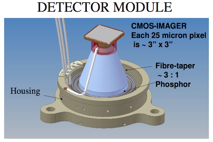
Fig. 2.19 : Configuration of the detector module is shown. At the bottom, and hidden by the housing, are the 5 mm thick window with photo-cathode deposited on it, and a set of two micro-channels-plates for multiplication ( by up to about a million) of the photo-electron. The electrons are accelerated by ~ 5 kV and strike the phosphor to emit a pulse of photons. The light from phosphor is transmitted to Star-250 (C-MOS Imager) by a fibre-taper. The fibre-taper also matches the 40 mm diameter of the window to size of the C-MOS Imager (512 X 512 pixels of 25 X 25 microns).
Gap between the photo-cathode and micro-channel-plates is kept small (~ 0.1 mm ) to minimize drift of the photoelectrons. With such small gaps, contribution of the detectors to the PSF is no more than ~ 1” FWHM.
The detectors can either be operated in photon counting mode (with a very high multiplication by the micro- channel-plates) where a list of coordinates of centroids of the detected photons is transmitted, or in integration mode with the multiplication kept at a low value where the raw frame of CMOS is transmitted. Typically the ultraviolet detectors are used in photon counting mode and the visible detector is used in integration mode. Either the entire array of 512 X 512 pixels can be read, at a max. rate of ~29 frames/s, to capture the full field, or a part of the field can be read in “window” mode at rates up to ~600 frames/s, depending on area of the window.
-
Thermal Effects
Variations in temperature can effect observations in several ways. Relative thermal expansion shifts focus of the telescope, and surface of the mirrors can get distorted. To minimize these effects, temperature of the telescopes is kept 200 +- 30 C and the structure is made of Invar. The mirrors are mounted on flexible supports made of Invar to minimize thermal stresses. There is no provision for adjustment of the focus in orbit, but the effect of temperature variations on the focus is expected to be small.
Transmission of the filters/gratings and quantum efficiency/gain of the detectors too can change with temperature. The temperature of these elements is kept in range 150 C to 300 C. The thermal effects are not calibrated on ground. As the photon counting mode is not very sensitive to the gain of the detector, this mode is affected less than the integration mode.
Correction for the drift is based on assuming that there is no relative drift between the three channels. Temperature variations can lead to relative drift between the channels, and this can only be modeled with in- orbit data.
Backgrounds
UVIT background has several sources. These are discussed below.
a) Dark counts in the detector:
At 20 degree C the dark photon counts are (as per the test data from Photek, UK , who supplied the CPUs of the detector systems):
VIS NUV FUV
1266/s 50/s 8/s
b) Bright limb of earth
At angles less than 45 from the axis, bright earth can give background which is in excess of the Zodiacal light.
c) Zodiacal light
Zodiacal light is ~ mag 22 per sq arcsec in the V band. This corresponds to ~ 5 x10-18 erg/(s A cm2 arcsec2) or ~ 0.08 detected photons per second per sq arcsec for an effective area of 50 sq cm for a band 5500 A to 6500 A.
This background falls very slowly between 6000 A and 3000 A and it falls very fast at the shorter wavelengths. The photon flux per A is less by ~ 6 (300) at 3000 A (2000 A) as compared to that at 6000 A.
d) Geocorona
Geocoronal lines are excited by solar radiations and vary in intensity by large factors. Typical counts of detected photons in the detectors, without filter, are listed below:
.
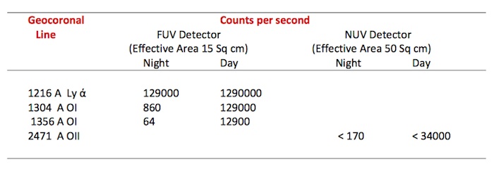
It is clear that due to these lines observations cannot be made during the daytime in FUV channel. Further, the CaF2 filter (the widest band filter in FUV) could have leak of a few percent for Ly ά, and the nighttime counts could be in range ~ 1000/s to 5000/s.
Photon Counting and Integration Modes
The detectors can operate in two distinct modes: i) Photon Counting Mode
ii) Integration Mode
In the photon counting mode, a very high multiplication is obtained in the MCPs such that each photo- electron generated in the short exposure (<100 ms) is detected as a light pulse in the CMOS imager, and its centroid is found. Thus, for each frame of exposure a list of centroid-positions is obtained from the detector. The expected spatial resolution in this mode is < 1.8” FWHM.
In the integration mode, multiplication of the MCPs is kept low, and signals in all the pixels of the CMOS detector are obtained. In this mode, many (weak) pulses of light, from many photo-electrons, could fall at the same location; the signal at any location is a measure of how many photo-electrons were detected.
Photon counting mode gives a much better spatial resolution (<1.8” FWHM for FUV and NUV channels) as compared to the integration mode (~ 5” FWHM) . However, if in a single exposure two or more photon events occur within a separation ~< 3 pixels of the CMOS imager (~ < 10”), these are detected as a single event or rejected as unacceptable event (see later discussion on choice of modes).
For imaging full field, minimum exposure time is ~ 34 ms. Therefore, given the background levels, imaging in the VIS channel in photon counting mode would lead to overlapping photon events. Further, the total flux of visible photons is such that in photon counting mode life of the MCPs would be exhausted in about one year. Hence, imaging in the VIS channel is normally done in integration mode.
-
Operational Constraints
Avoidance of ram-angle, Sun, and bright-Earth for safety:
In order to avoid any damage to coating of the primary mirror, due to atomic oxygen, a minimum angle of 120 is kept between the ram direction and the roll-axis, i.e. axis of UVIT. In order to avoid damage/UV-assisted contamination due to radiation from Sun/bright-Earth, a minimum angle of 450 / 120 is kept between the axis and Sun / bright-Earth at all times even if UVIT is not observing.
Avoidance of bright objects:
Every field to be observed is checked for avoidance of very bright objects in a neighborhood of 20 radius; from 20., 1 part in 104 of the FUV flux could be scattered in the field.
Saturation with bright objects:
Any bright object which can give a detected photon count rate >1 count pr frame per ~ 10” X 10” would see serious saturation effects. Thus, to observe relatively bright objects in photon-counting mode a high frame rate can be used with partial field of view. (Minimum exposure time for the full field is ~ 34 ms, and it is ~ 2 msforafieldof6’X6’.
Choices in Photon Counting Mode and Integration Mode
The nominal mode of observations for the ultraviolet channels is photon counting. Due to its large background, nominal mode of observations in the visible channel is integration mode with a low gain of MCP. To observe bright sources in the ultraviolet, either a high frame rate with a reduced (windowed) field can be used or the integration mode can be used. (As mentioned earlier, the spatial resolution in the integration mode is ~ 5” as compared to < 1.8” in the photon counting mode.)
In the photon counting mode a set of choices are available, in the hardware of the detector system, for selecting: a) thresholds for signals, in the pixels of Star250, to define a genuine photon event, and thus reject noise; a large threshold would reduce effective quantum efficiency, while a small threshold would bring in more noise-events, b) choice of centroiding algorithm for the events from a 3 square/5 square/3 cross windows. In addition, during the ground processing, a threshold can be set for rejecting bright pixels at the corners of the events to eliminate close pairs of photon events – this is required to minimize errors in determination of position of the centroid.
In the integration mode, the hardware allows selection of the gain of MCP by control of the high voltage. Thus, for a very bright source a very low gain can be selected to avoid saturation of the pixels of Star250.
Observing in Partial Fields
For the full field (~ 28’ circle), the maximum double frame rate is ~ 29/s. For those sources which have an intensity > ~ 5 photons/s/(10” X 10”), many frames would have close double photon events at this frame rate. In order to avoid double photon events for such sources a higher frame rate can be obtained by selecting a partial field for observations: the field is selected in units of pixels of Star250. The maximum frame rate is roughly in inverse proportion to area of the field. Thus, given the full field as 512 X 512 pixels, a rate of >600 frames/s is obtained for a field 100 X 100 pixels.
-
Soft X-ray Telescope
Soft X-ray imaging Telescope (SXT) onboard Astrosat will be sensitive to soft X-rays in the energy range of 0.3 − 8 keV. X-rays in this energy range are amenable to focusing and will lead to: a) nearly 1000 times better sensitivity over non-focusing instruments of similar areas making over 10,000 sources detectable; b) separation of confusing sources; c) arc min imaging; d) spatially resolved spectroscopy; and e) variability studies.
SXT will cover a very important energy range of the broadband spectrum observed with Astrosat, and will be able to investigate the following scientific problems.
1. Resolving the K line emission from Si, S, Ar, Ca and Fe in hot thermal coronal plasmas, as well as
fluorescent line emission from these elements in the medium photo-ionized by strong X-ray continuum in accretion powered X-ray sources (neutron stars, stellar mass black-holes, supermassive black-holes etc.).
2. Carrying out spectroscopy of hot thin plasmas in galaxies, clusters of galaxies, nuclei of active galaxies, quasars, supernova remnants and stellar coronae.
3. Studying the physics of shocks and accretion disks, coronae, photo-ionized regions and their density, temperature, ionization degree, and elemental abundance.
4. Studying low energy absorption and the nature of absorbers, for example, whether these are cold (neutral) or warm (ionized).
5. Studying soft X-ray excesses due to a blackbody emission in AGNs, and in binary X-ray pulsars in conjunction with other higher energy X-ray instruments.
6. Carrying out Spatially resolved spectroscopy of Supernova Remnants and Clusters of galaxies.
7. Carrying out simultaneous wide-band spectral studies and time-resolved spectra of thermal as well as non-thermal plasmas in the universe using the unprecedented combination with
sensitive hard X-ray detectors.
Telescope
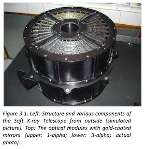
The telescope consists of a tubular structure housing the X-ray reflecting mirrors and other components. There is a “Charge Coupled Device” (CCD) camera at the focal plane of the mirrors in order to image the cosmic sources.
Basic Components
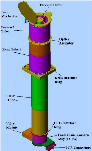
The basic components of the telescope (apart from the mirror assembly) are given below (see Fig. 3.1).
a) A deployable cover/door at the top end of the telescope which covers the optical elements on the ground and protects them from contamination. It will be deployed in 4 to 6 weeks after launch. It can be closed only manually on ground. Once opened in space, it will be deployed at an angle of 270o.
b) A “Thermal Baffle” placed between the mirror assembly and the telescope door. All parts are made up of aluminum alloy 6061 T6. The function of thermal baffle is to protect the telescope from the Sun, and to provide a base for mounting the heaters to maintain the optics within a certain specified range of temperatures, and to block the unwanted area of the optics. The sun avoidance angle with the thermal baffle is ~45o.
c) A “Forward tube” made up of Composite Fiber Reinforcement Plastic (CFRP). Forward tube extends from the bottom of the “Top Lid”. It covers the thermal baffle assembly.
d) Ring 2 as an interface ring between the forward tube and the middle flange of the optics. Ring 1 provides an interface between the Rear tube-2 and the middle flange of the optics.
e) Rear tube-1 made up of CFRP is a hollow cylinder of diameter 343 mm ID and 347.8 mm OD. Rear tube-1 extends from Ring-1 to “Deck Interface Ring” (DIR). It houses 3α Optics while forward tube is the house for 1-alpha assembly (see below).
f) “Deck Interface Ring” (DIR) is made up of Al alloy 6061 and is used to assemble rear tube-1 and rear tube-2 to the main deck of the satellite.
g) Rear tube-2 made up of CFRP is a hollow stepped cylinder with a top portion thicker than the bottom portion to provide stiffness. Rear tube-2 extends from the DIR to the CCD interface ring.
h) CCD interface ring is provided to align the CCD Camera with the tubular structure to the desired accuracy. This is made up of aluminium
alloy 6061.
.
Using ASTROSAT as a broad-band Observatory
So far we have discussed the details of individual payloads on ASTROSAT and its capabilities. However, since all these experiment are co-aligned (except SSM) and mostly operates in unison, ASTROSAT can effectively conduct broad-band multiwavelength observation from Optical to hard X- rays for select sources in the sky. Here we explore briefly the nature of such potential investigations.
For correlated variability in soft and hard X-rays use time tagged photons data from SXT and LAXPC.
• Correlated variability in X-ray and UV bands require time tagged data from X-ray instruments and fastest possible photometric data from UVIT.
• To study simultaneous broad-band X-ray spectrum from 0.3-100 keV, combine data from SXT, LAXPC and CZT and perform simultaneous spectral fits in XSPEC (X-ray analysis package).
• Search of Cyclotron absorption feature (usually in ~10 keV to 60 keV ) needs well calibrated spectral data with high statistics from LAXPC and CZT instruments.
• For constructing multi-frequency spectra (Spectral Energy Distribution) of AGNs, CVs, SNRs etc, simultaneous observations with all 4 instruments over a time scale less than the variability time of a source is needed.
-
Observing with ASTROSAT
Introduction ASTROSAT orbit Observing Constraints
• SAA
• Celestial constraints
• Sky Visibility
• Bright source avoidance
• Multiwavelength observations
Field of View of Instruments Instrument overheads
Observing Policies and Procedures
• ASTROSAT Time sharating plan
• Observing Cycles
• Proposal Types
• ToO proposals
• Proposal review process and time allocation
-
Quelle: ISRO
4855 Views
