
13.01.2018
Weiteren Background von Mick West/Metabunk zur F-18-FLIR-Video-Aufnahme der NYT-Story:
...
+++
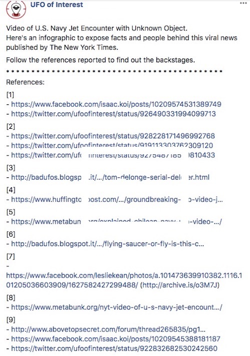
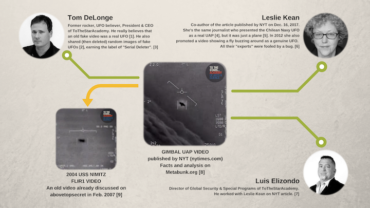
NYT: GIMBAL Video of U.S. Navy Jet Encounter with Unknown Object
+++
Another source of info for the ATFLIR obsessed is Raytheon's patents.
https://patents.google.com/?q=gimbal&q=IR&q=rotation&q=visible&assignee=raytheon
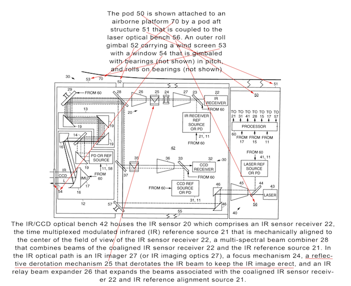
https://patents.google.com/patent/US6288381B1/
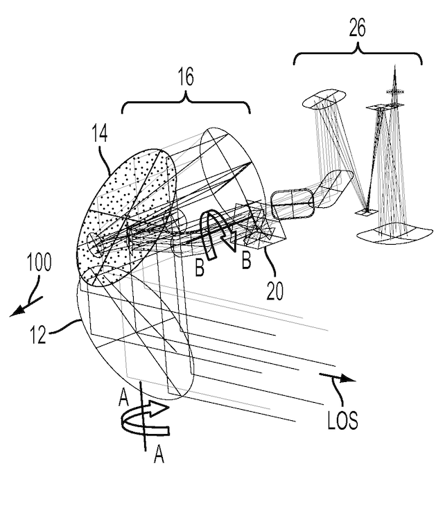
The following diagram is a schematic of an ATFLIR, with the nose (and hence the windows) on the left. It explains that the image is "derotated" by a "a reflective derotation mechanism 25" (and another for the visible light at 35).
+++
I believe the portion of the system you show is the rearward portion...
A Raytheon patent you linked to, which seems to be for the forward camera in the ATFLIR, says 'gimbal lock' can occur when LOS = 0˚ (which is also "roll axis BB"), and to avoid that gimbal lock, rotational adjustments are made...
[0035] ... The situation where the LOS is precisely parallel to roll axis BB and thus causing the roll axis BB to not steer the LOS is called a “gimbal singularity” or “gimbal lock.” A control gain of roll axis BB is proportional to 1/sin α. Hence, the gain of roll axis BB can go to infinity when α is equal to 0, i.e., when the LOS is precisely parallel to roll axis BB. From the standpoint of an automated control system 90 (shown in FIG. 1) for controlling the orientation of c-mirror 12, i.e., controlling the rotation around roll axis BB and rotation around axis AA, this gimbal singularity may be problematic because no amount of rotation around roll axis BB produces any desired effect of steering the LOS.
[0036] As a result, in certain applications, the gimbal singularity is to be avoided. However, in an embodiment, where the gimbal singularity cannot be avoided, for example because the gimbal singularity is within the desired field of regard (FOR), then it may be desirable to provide a third gimbal axis TT (shown in FIG. 1). In one embodiment, third gimbal axis TT is within the plane of c-mirror 12 and is perpendicular to rotation axis AA. In one embodiment, the third gimbal axis TT resides on rotation axis AA of c-mirror 12 in that a rotation of c-mirror 12 around axis AA produces a rotation of axis TT. The third gimbal axis TT can be of small angular travel (for example, less than or equal to 5 deg.). As a result, axis TT travels around roll axis BB and avoids the gimbal singularity.
[0037] For example, when an object being continuously tracked by moving c-mirror 12 in various directions by rotating around rotation axis AA and/or around roll axis BB and/or optional third axis TT using control system 90 is projected to go close to or through the gimbal singularity, and optional third gimbal axis TT is provided with a range of angles α, for example, ±3 deg, roll axis BB is no longer used for tracking the object within the ±3 deg. range that surrounds the gimbal singularity. Instead, rotation axis AA and third gimbal axis TT are used to continue to track the object within the ±3 deg. angular range. When, on the other hand, the object location exceeds, for example, the 3 deg. singularity, roll axis BB is used by control system 90 in the tracking motion. In this case, the third axis can be gradually returned to 0 deg. and no longer has involvement in the tracking motion. In other words, control system 90 controls the tracking by rotating c-mirror 12 around third gimbal axis TT when an object is located closely around the singularity (e.g., within the ±3 deg. range). Otherwise, when the object is outside the ±3 deg. range around the singularity, control system 90 controls the tracking by rotating roll axis BB and leaving the third axis TT fixed or returning third axis TT to 0 deg.
If I'm reading that right, it says rotational adjustment in the optics are made as the LOS sweeps across 0˚.
A homespun example of gimbal lock...
+++The gimbal housing has two separate windows one for the Laser Spot Tracker and the second for EO/IR.
But the figure shows 54 as one common window for both laser and IR together, just like the boresight aligned path that patent involves, and the Raytheon animation shows the aligned path to feed into the rear 'camera'.
Patent 20120292482A1 in contrast shows the LOS to targets...
You are saying the blue line should shoot out the path along which the yellow line enters the front, but it does not. The only place we see the blue and yellow lines overlap is feeding into the rear set of components, matching window 54 in Patent 6288381B1.+++![[IMG]](https://www.metabunk.org/data/MetaMirrorCache/63333f70e2e5e0067bf1354677d92f6f.gif) +++
+++![[IMG]](https://www.metabunk.org/data/MetaMirrorCache/af851a4052b2a8a351e8c697e0603ffd.gif) +++
+++
Martin Willis Live Shows 1 hour ago
Wouldn't they know if the craft filmed had a transponder or not?
Of course we only get a 30-second glimpse into the gimbal-video cockpit. So how quickly one might expect to receive transponder data is a relevant question. Is transponder data expected to appear along with any target immediately (I suspect not), or is it given only upon interrogation?
Another point is, given we have no location data, we can't rule out that the other aircraft or the alleged "fleet of them" are from a foreign military. These pilots might, for example, be flying near China or Russia.+++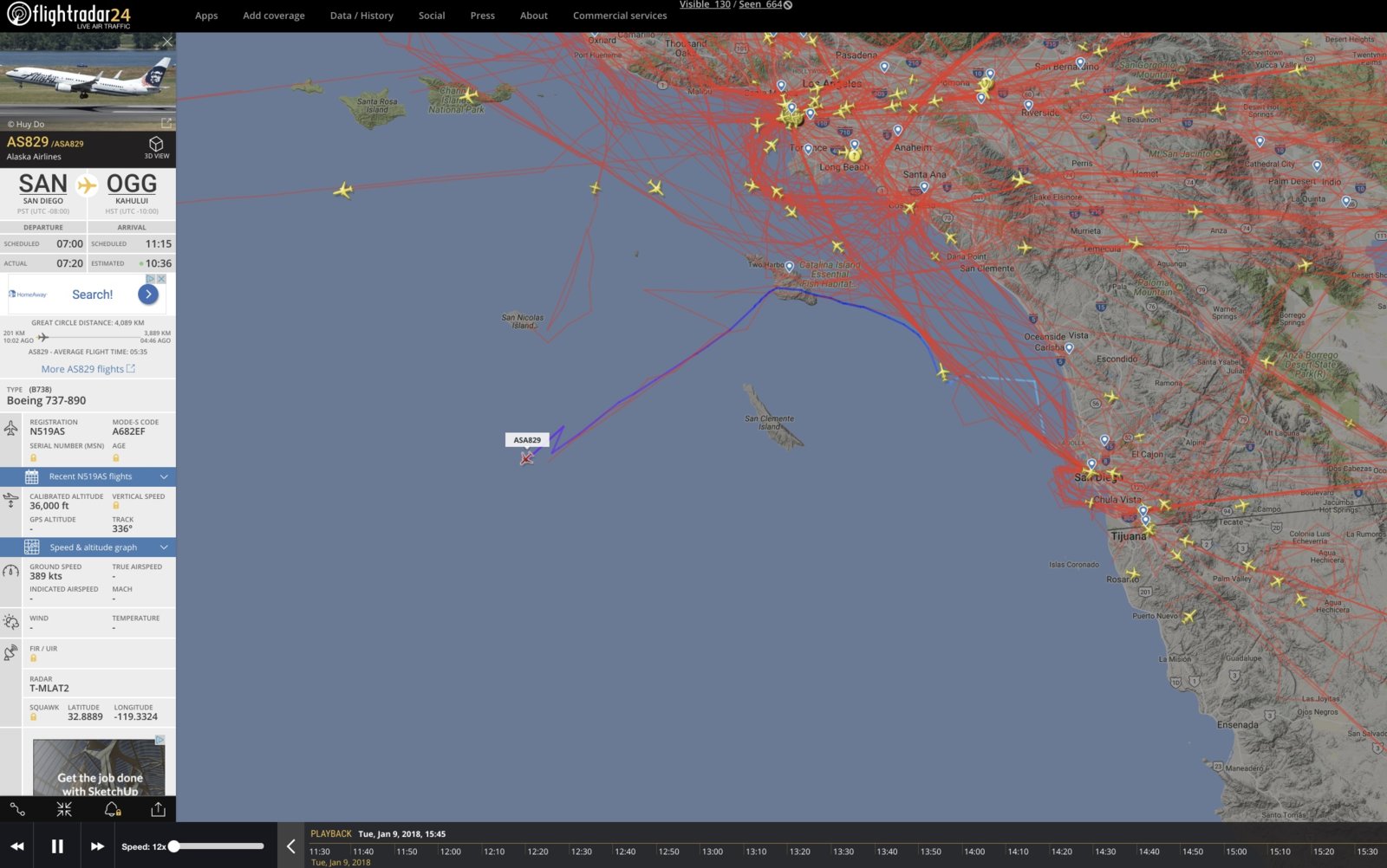 +++I agree. These "pilots" might also, for example, be voice actors.
Excellent point! What data was used to rule out that the audio recording of the alleged "pilots" isn't fake?+++
On the other hand, I don't think we have any particular reason to suspect the audio is faked, but given the people involved in the TTSA enterprise and its "mission", it could very well be.Quelle: Mick West, Metabunk
![[IMG]](https://www.metabunk.org/data/MetaMirrorCache/fd7e77fa2fc2037fc267761d11c06887.jpg)
![[IMG]](https://www.metabunk.org/data/MetaMirrorCache/9e30b0a890f096f59609dfe063f16222.jpg)
![[IMG]](https://www.metabunk.org/data/MetaMirrorCache/6eb87bdc65c5eb97ebf00f0cd5b0dcfa.gif)
5500 Views