
.
60-Inch Diameter 21 Percent Missile
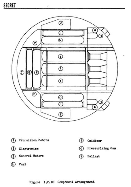
The electronics section, consisting of the guidance, autopilot, fuze, adaption kit (when a nuclear warhead was employed), and power supply, was in the thin forward end of the missile. Two structural beams extended from the leading edge to the rocket motor forward bulkhead to provide aeroelastic body stiffening and attachments for mounting electronic packages.
A detailed study was conducted in future trends for electronic components that showed the increased future capability possible.
Interchangeable nuclear or shaped-charge conventional high explosive warheads would be suspended between the two forward beams. It was determined that a nuclear warhead would be available during the Pye Wacket development time period which could be adapted to the 21 percent missile.
The integral rocket motor for the nominal configurations was a pancake type of basic thick skin construction. The solid propellant motor burned at 250 PSI chamber pressure. This thick skin utilized a honeycomb or waffle type construction. This resulted in reduced structural weight and increased strength since the external skin of the rocket motor formed an integral part of the missile aerodynamic surface.
The leading edge consisted of laminated construction. Over the steel edge joint an insulating material was attached which supported the actual leading edge of carbon. The entire section was covered by ablation materials. This leading edge extended over the forward 180 deg of periphery of the missile. The edge around the remaining aft portion of the missile was constructed of honeycomb material in the same manner as the skin.
The reaction control system was packaged in the aft end of the missile on both sides of the main nozzle. These reaction controls operated by means of four fixed nozzles which exhausted through the top and bottom aft surfaces. Pitch, yaw, and roll control were obtained by differential throttling of the propellant flow to the four fixed combustion chambers.
The entire reaction force system including propellant, pressurizing charge, servos, and thrust chambers would be constructed as an integral package for installation into either side. Electrical signals to control propellant flow were transmitted from the autopilot in the electronics section to the aft section via electrical harnesses inside the periphery of the missile.
The main motor swivel nozzle with 10 deg of action in both pitch and yaw provided additional control forces during the boost phase of flight. A final design might need thrust vector control in one plane. Mass injection could be substituted for nozzle swiveling. Openings in the top and bottom skins over the nozzle exit region allowed the nozzle to extend outside the missile contour when deflected in the pitch plane.
Electrical connection to the launcher and location of the umbilical connector would depend on final design of the launch mechanism. Obviously the originally-planned center-threaded hole might be difficult in the pancake motor design.
The missile skin could be easily removed in two major sections by disconnecting a main joint across the forward edge of the rocket motor. This allowed easy access to all components for assembly, test, checkout and servicing. To insure reasonable skin temperatures the entire external surface was covered by an ablative material of varying thickness as required by aerodynamic heating considerations.
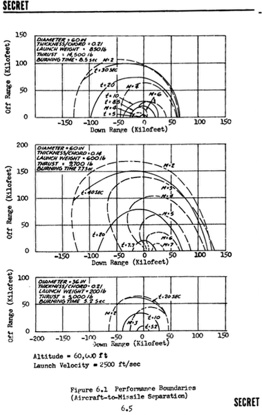
The 60-inch diameter 21 percent thickness ratio missile had a launch weight of 530.4 pounds and an empty weight of 324.4 pounds.
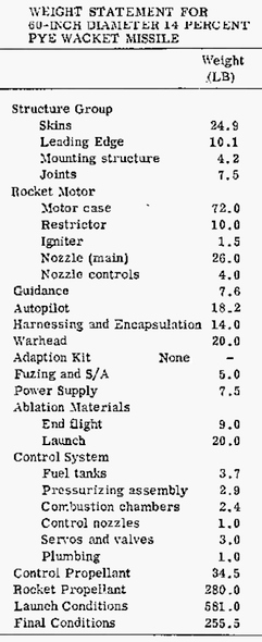
60-Inch Diameter 14 Percent Missile
The 60-inch 14 percent missile was less capable due to the lower missile mass.
36-Inch Diameter 21 Percent Missile
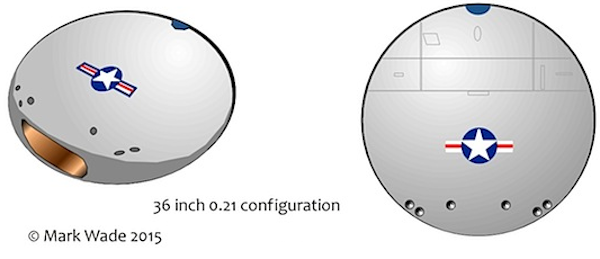
A feasibility design was conducted on a smaller 36-inch Pye Wacket missile. A 21 percent thickness-to-diameter ratio was chosen to facilitate component packaging while affording the greatest reduction of diameter. The simplified fuze was an active fixed angle type which optimized the fuzing problem for maximum kill probability. The fuze package and the guidance package would be encapsulated and electronically shielded by means of direct deposition of metallic film. The safe and arm mechanism provided positive safing under all conditions of shipment and handling. Arming could not occur until the missile had experienced the proper boost acceleration in the proper direction for a specified length of time.
The warhead was centrally located between the forward rocket motor bulkhead and the guidance package. Warhead support was furnished by attachment to the forward mounting beams. A nuclear warhead as favored by Eglin could not be accomodated in the small volume available in the 36 inch design. Instead a 20-pound controlled fragmentation warhead which fit the missile contour and employed flat aft and front surfaces was chosen.
A pancake type solid propellant rocket motor and a reaction control system similar to those for the 6O-inch diameter missile were assumed.
To better illustrate the packaging arrangement of the 36-inch diameter missile a conceptual mockup was constructed.
Other Applications
Omnidirectional launch and excellent performance characteristics made manned-aircraft defense the most promising application for Pye Wacket. However Pye Wacket could also be a game-changing all-purpose air-to-air and surface-to-air missile. Interceptor aircraft could launch Pye Wackets simultaneously against multiple targets in a dispersed formation of oncoming bombers at ranges of up to 40 miles and altitudes of up to 120,000 feet. Use of Pye Wacket as an air-to-surface tactical weapon would allow aircraft to attack targets far from the line of flight at extremely large offset ranges. Air-to-air ranges were based on attacking air targets at the same altitude as the launch aircraft with the missile still at Mach 2. Therefore supersonic ground impact points well in excess of these distances were possible with Pye Wacket.
The Pye Wacket configuration would also provide an ideal manned spacecraft. Pye Wacket would function as a blunt body for re-entry when at an angle of attack of 90 deg. Following the maximum phase of heating and deceleration it would pitch over and provide a high lift body at small angles.
Development Plan
It would not be possible to proceed with a production design without a great deal of additional analysis and laboratory testing leading to flight test of a prototype. The acquisition of experimental aerodynamic data for design purposes had barely begun. Lift, drag and stability information had to be obtained from low speed to the hypersonic range. Yaw data was needed in the entire range from 0 to 180 degrees with a simulated jet-on condition. Much work was needed to develop a stable launching system that provided sufficient ejection velocity. Interactions between the propulsion system, basic structure, and the thermal protection required thorough investigation to establish a compatible group of solutions. The tradeoff between technical maturity, development time, cost, reliability, logistics, and operations had to be considered prior to determining whether the propulsion system should use solid or packaged liquid propellants. Testing of structural models would be necessary to establish the dynamic and static characteristics. These results in turn might affect the rocket motor operating pressure and motor performance.
Ablative materials and methods of applying these to the basic structure had to be analyzed and verified by experimentation. Solving fabrication and application of refractory materials to the leading edge of the vehicle required solutions. Aeroelastic investigations were necessary to enable the establishment of dynamic structural performance limits.
The development of a workable control system that provided artificial stability would be fundamental to the success of the Pye Wacket concept. Work to establish acceptable reaction jet time constants was needed. Wind tunnel studies were necessary to study interaction of the jets with airflow and the best reaction jet orientation.
Flight testing would be mandatory to demonstrate stabilized controllable flight by means of a reaction jet control system and omnidirectional launch capability. Off-the-shelf components would allow the concept to be proven and refined prior to committing to a production design. It was proposed that a series of ground-launched vehicles would be used to test basic vehicle performance and stabilization. This would be followed by three lots of missiles fired from a supersonic rocket sled to verify and refine the omni-directional launch capability.
Pye Wacket Phase II
In line with the recommendations of the first report, the next year was spent designing a Feasibility Test Vehicle (FTV). The three-volume, 595 page result was completed on 15 February 1961. The FTV was a version of the 60-inch design that could be could be fabricated in a short time with off-the-shelf components and existing solid rocket motors for launch by rocket sled
Aerodynamic data obtained during 80 hours of wind tunnel testing at Arnold Engineering Development Center, Tullahoma, Tennessee used two heavily instrumented 1/3-scale models. One was instrumented to measure forces and moments and the other to measure the body pressure distributions.
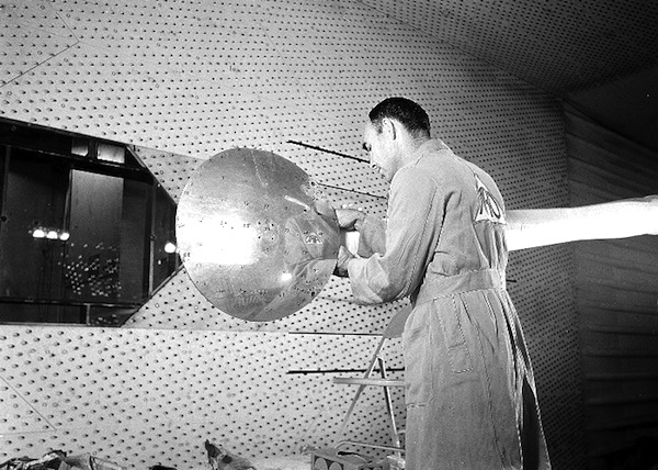
The pressure model simulated the pitch and roll reaction control jets with cold gas at chamber pressures ranging from 100 to 1000 psia. The models were tested at Mach numbers ranging from 0.6 to 5.0, at angles of attack from 0 to 15 degrees and at sideslip angles from 0 to 180 degrees.
The reaction control system was studied extensively with special attention on obtaining the high thrust level with the required response time. Reaction control studies culminated in the requirement for a 500-pound thrust level and a 5 millisecond response time. Existing systems had neither the thrust levels or response time required for the FTV. A Convair company-sponsored test program of the response obtainable with an existing 300-pound thrust motor identified the development work required to meet FTV requirements. These tests, together with the results of an industry survey, indicated development of a system for the FTV in a short period would not be difficult.
The aerodynamic test data allowed a definitive structural design to be made. Together with the reaction control system studies, this then allowed a detailed simulation of the stabilization and control system for the missile.
The resulting autopilot had to fully exploit the unique properties of this configuration using a nonlinear control philosophy. The aerodynamic moments were of such a magnitude that four control motors would be required for pitch and and four for roll. The autopilot was studied primarily in forward, crosswind and aft launch conditions. Autopilot parameters were verified on a time varying three-dimensional simulation.
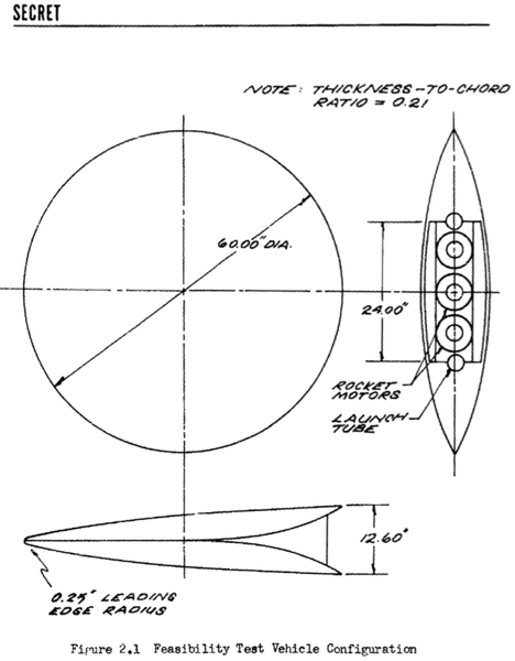
The resulting Pye Wacket Feasibility Test Vehicle design was 60 inches in diameter with a 21% thickness-to-chord ratio. The maximum thickness of 12.6 inches occurred at the blunted trailing edge. The main propulsion was provided by three M58A2 rocket motors. The M58A2 was in production for the Falcon missile, was readily available, and had demonstrated a high degree of reliability. These motors would boost the FTV from the rocket sled speed of 550 mph to over Mach 2.
FTV Weight Summary
Structure: 66 lbs
Reaction Control Propellant System: 37 lbs
Reaction Control Propellant: 35 lbs at launch, 18 remaining at burnout
Reaction Control Motors: 30 lbs
Electronics: 40 lbs
Booster motors: 137 lbs at launch, 42 lbs at burnout
Miscellaneous: 11 lbs
Ballast: 69 lbs
Total: 425 lbs at launch, 313 lbs at burnout, 295 lbs empty
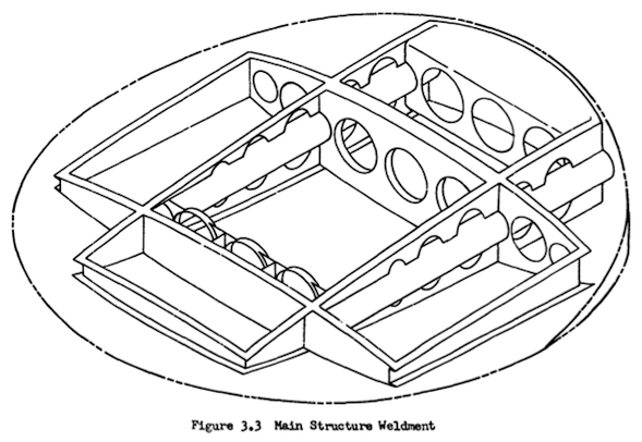
The main structure weldment of the Feasibility Test Vehicle was four magnesium alloy (AZ 31B) channels criss-crossing the missile planform. This weldment, when coupled with the missile skin, provided structural rigidity in all planes. The launcher tubes and booster support were an integral part of the weldment in order to ensure maximum alignment. The cast magnesium-alloy skin could be removed to allow access to all components for easy assembly, checkout and servicing.
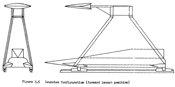
The launcher was a twin-rail system capable of 360 degree rotation in the horizontal plane and 90 degrees in the vertical plane. The launcher rails slid into two longitudinal cylinders on either side of the booster motors. The launcher design incorporated sufficient ground clearance to allow at a 100% safety margin beyond the predicted missile "drop-off" during aft launch.
Pye Wacket Phase III
The Phase II report recommended authorization of a Phase III flight test program to demonstrate proof of the basic concept. Convair proposed fabrication and flight test of 12 FTV's from a high speed sled. In addition to proof-of-concept, the flight test program would provide important data on transients encountered at launch in maneuver, and test the non-linear autopilot and high response reaction control system.
The first six months of the Phase III effort would concentrate on development and proof-testing of the autopilot and reaction control system. At the same time fabrication drawings for the FTV and test sled would be produced based on the Phase II configuration studies. Following fabrication, flight tests would be conducted using the high speed sled at the Edwards Flight Test Center Facility (the Hurricane Mesa Facility mentioned in some earlier Pye Wacket accounts had already been shut down). Flights from the sled would be made for forward, side, and aft-launch conditions. Photographic coverage would be obtained as well as data from the missile telemetering system and ground surveillance.
A further recommendation was that the USAF issue a specific requirement for a weapon which could exploit the inherent advantages of the Pye Wacket concept. This would expedite development of the weapon and advance its operational availability date.
Although some have speculated that at this point Pye Wacket went black and was in fact developed, by the time Phase II was completed in February 1961 the United States had a new President, John Kennedy, and a new Secretary of Defense, Robert McNamara. McNamara, accountant, formerly and briefly head of Ford Motor Company, proceeded to cancel every single innovative defense program in sight. High speed bombers and interceptors, nuclear-powered aircraft, missiles, and spacecraft, all were axed or scaled back to low-cost study efforts. Active bomber defense was dumped. The accountant's approach was to use existing B-52's for low-altitude penetration under the radar while waiting (and waiting) for the F-111. In this environment it is doubtful that Pye Wacket hardware advanced beyond the end of the Phase II study.
It was not quite the end, however... things were afoot in the black world after all...
Quelle: Encyclopedia Astronautica